
VHF Audio/Video Sender
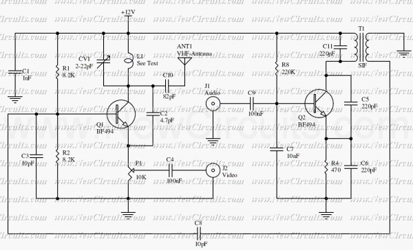
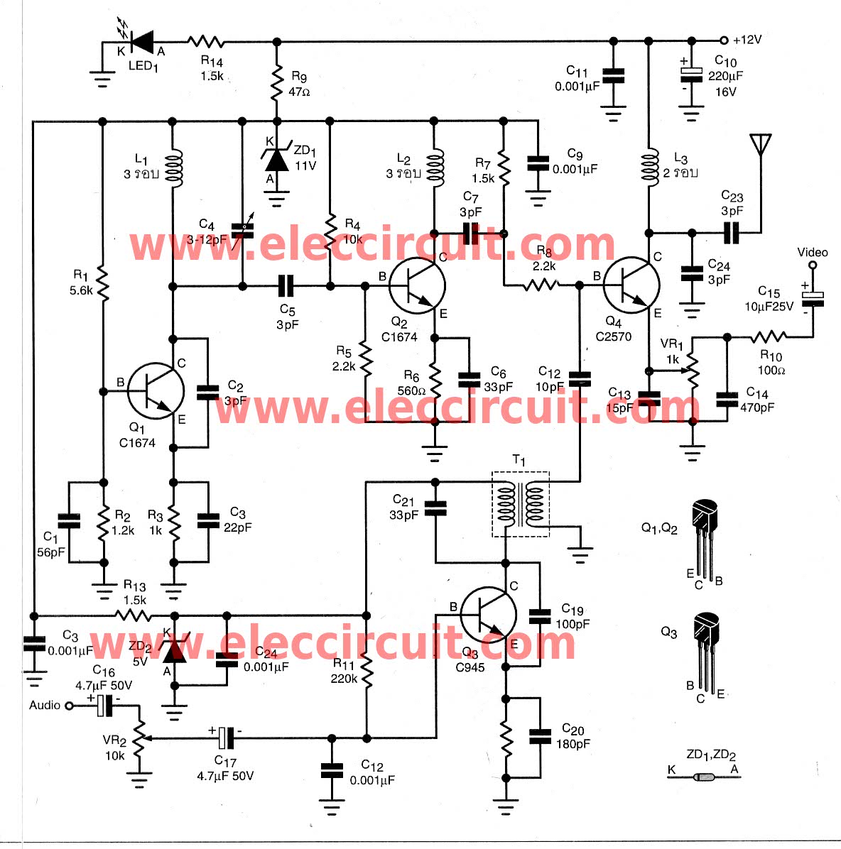
The circuit described serves as a basic audio/video transmitter designed to operate within a range of 3 to 5 meters. The A/V signal source can include devices such as VCRs, satellite receivers, or video game consoles. The primary function of the circuit is to modulate the audio and video signals for transmission over VHF frequencies, specifically tuned to channel 5.
The circuit employs a mixer that doubles as an oscillator, which is crucial for generating the desired carrier frequencies. The video signal modulates the amplitude of the carrier wave, which operates at a frequency of 175.25 MHz for video and 180.75 MHz for audio. This modulation technique allows for the transmission of audio and video signals simultaneously, enabling the receiver to decode and reproduce the original signals accurately.
The transmitter utilizes a transistor, designated as Q1, which is integral to the oscillation process. Q1 is connected to a resonant tank circuit composed of inductor L1 and a variable capacitor (VC1). This combination allows for fine-tuning of the oscillator to ensure it operates at the precise frequency required for VHF channel 5. The resonant circuit's design is critical, as it determines the stability and quality of the transmitted signal.
Additionally, transistor Q2 is included in the design, which further enhances the circuit's performance. Q2 works in conjunction with a tuned circuit formed by a SIF coil and an inbuilt capacitor. This configuration aids in filtering and amplifying the modulated signals, ensuring that they maintain integrity over the transmission distance.
The overall design adheres to the B-System standards set by the CCIR (International Radio Consultative Committee), ensuring compatibility with other broadcasting equipment and receivers. This compatibility is essential for effective communication between the transmitter and various A/V devices, allowing for a seamless user experience.
In summary, the circuit is a compact and efficient audio/video transmitter that leverages VHF technology to deliver quality transmission over short distances while maintaining compatibility with standard broadcasting systems.The circuit presented here is a simple audio/video transmitter with a range of 3 to 5 metres. The A/V signal source for the circuit may be a VCR, a satellite receiver or a video game etc. A mixer which also operates as an oscillator at VHF (H) channel 5 TV frequency is amplitude modulated by video signal and mixed with frequency mo enna, contains video carrier frequency of 175.25 Mhz and audio carrier frequency of 180.75 Mhz. Then, the transmitter is a B-System of CCIR compatible. The circuit consists of transistor Q1 with its resonant tuned tank circuit formed by inductor L1 and trimmer capacitor VC1, oscillating at VHF (H) channel 5 frequency. Transistor Q2 with its tuned circuit formed using SIF coil and inbuilt capacitor forms 🔗 External reference
Related Circuits
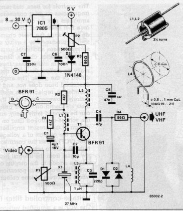
A simple oscillator generates a frequency in the VHF or UHF range. This oscillator is modulated with a video signal, and the resulting modulated carrier wave is transmitted to the TV set's aerial input through a cable. The final...
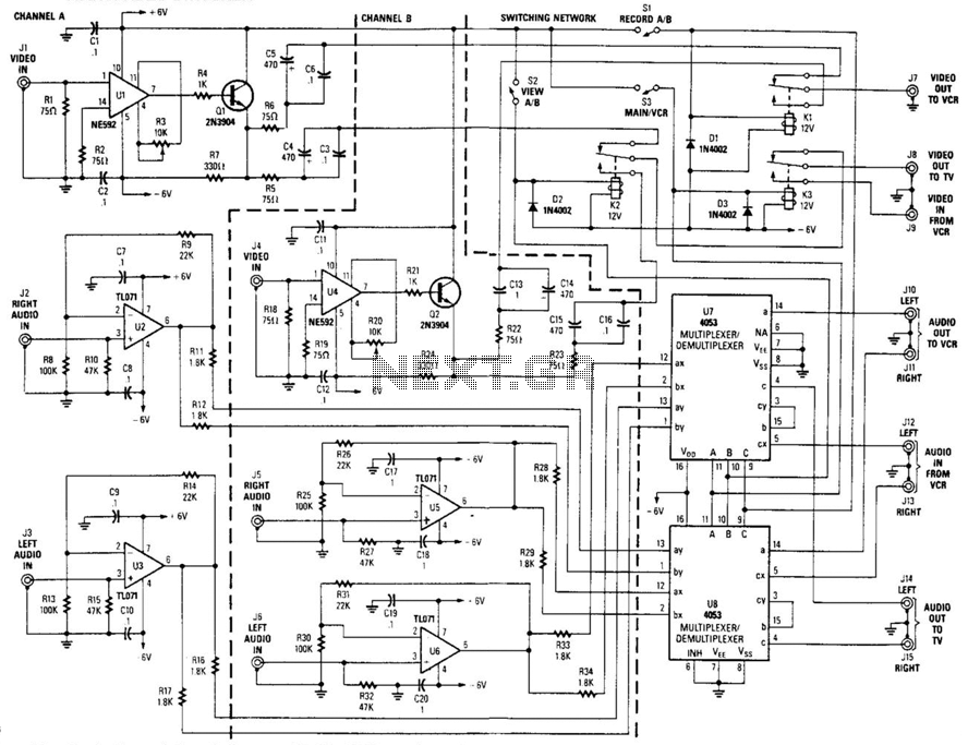
This circuit is a two-channel baseband video switcher. Buffer amplifiers U1/Q1, U4/Q4, and associated components produce a buffered 75-ohm video signal, which is routed to the switching network K1/K2/K3. Relay K1 selects either of the two video amplifiers and...
The PCB of this circuit should be positioned close to the antenna within a compact metallic enclosure. This VHF antenna circuit requires a 12 volts DC power supply, which can be sourced from a 12-volt battery, as the current...
The PMR VHF transceiver Motorola Radius M110 (in further text referred as M110) was manufactured by Motorola GmbH therefore being an European radio. Since many professional radio service users has replaced this transceiver with newer gear, a considerable number...
To transmit video and audio signals to multiple televisions simultaneously, a video amplifier splitter utilizing a transistor can be employed. A video amplifier splitter is an electronic device designed to distribute a single video and audio signal to multiple output...
The RF stage of the receiver utilizes a transistor VT1, functioning as both a mixer and a local oscillator while also serving as a synchronous detector. A headphone cable acts as an antenna, capturing signals that are directed to...
Warning: include(partials/cookie-banner.php): Failed to open stream: Permission denied in /var/www/html/nextgr/view-circuit.php on line 713
Warning: include(): Failed opening 'partials/cookie-banner.php' for inclusion (include_path='.:/usr/share/php') in /var/www/html/nextgr/view-circuit.php on line 713