
vhf antenna amplifier

The VHF antenna circuit is designed for efficient operation in the VHF frequency range, typically between 30 MHz and 300 MHz. The placement of the PCB near the antenna is crucial for minimizing signal loss and ensuring optimal performance. The metallic box serves not only as a protective casing but also as a shield against electromagnetic interference (EMI), which can degrade the signal quality.
Powering the circuit with a 12-volt DC supply is appropriate, given the low current consumption of less than 10mA. This low power requirement allows for the use of compact power sources, such as a 12-volt battery, which can be easily integrated into portable applications. The circuit may include voltage regulators or filtering capacitors to stabilize the power supply and prevent noise from affecting the circuit's performance.
The PCB layout should be designed with careful consideration of trace lengths and widths to minimize resistance and inductance, which can impact the circuit’s efficiency. Additionally, the use of high-quality components, such as low-noise amplifiers and precision resistors, will enhance the overall performance of the VHF antenna circuit. Proper grounding techniques should also be employed to reduce the effects of ground loops and ensure signal integrity.
Overall, this circuit configuration is suitable for applications requiring reliable VHF signal reception in a compact and efficient design.The pcb of this circuit must be placed near the antenna, in a small metallic box. This VHF antenna circuit must be powered from a 12 volts DC power supply circuit, you can use a 12 volt battery, because the current consumption of this circuit is very low under 10mA. 🔗 External reference
Related Circuits
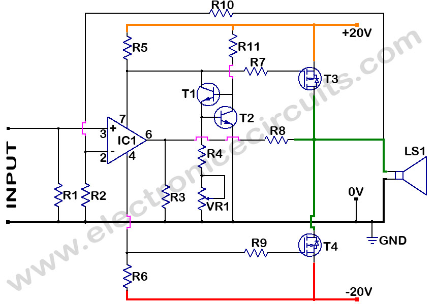
MOSFET Power Amplifier Circuit diagrams. Two complementary MOSFETs are used to deliver 20W into 8Ω. The described MOSFET power amplifier circuit utilizes two complementary MOSFETs, which are arranged in a push-pull configuration to efficiently amplify audio signals. The circuit is...
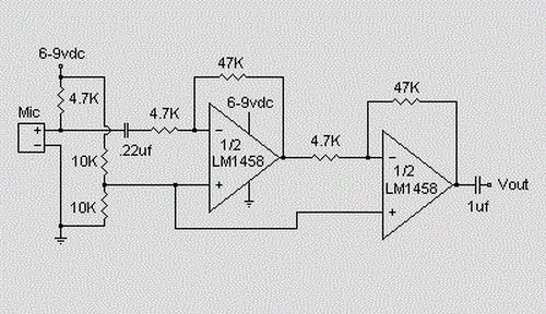
This is a simple preamplifier circuit designed for an electret condenser microphone, utilizing an LM1458 dual op-amp integrated circuit (IC). The circuit amplifies the audio signal from the condenser microphone, allowing it to be used as an input for...
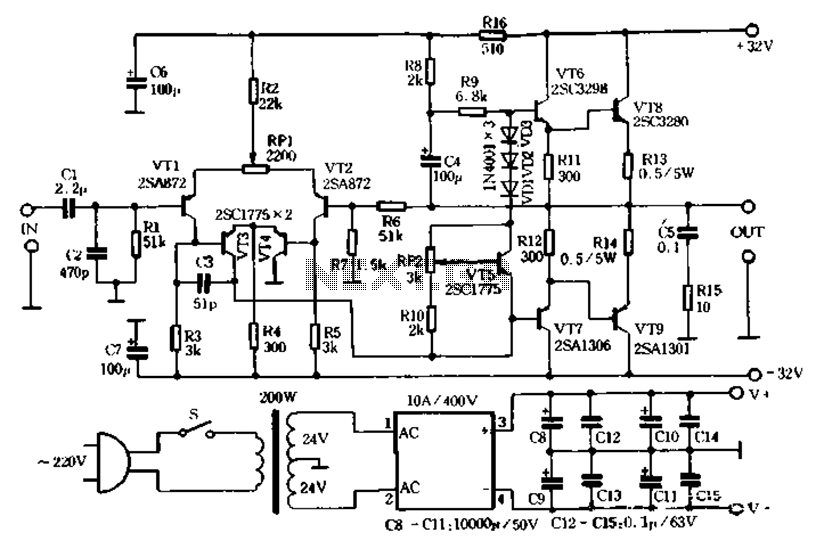
Fans are eager to create a high-quality amplifier; however, many of the most notable publications on the circuit tend to be overly complex and difficult to implement. This article describes a pure Class AB output stage amplifier circuit that...
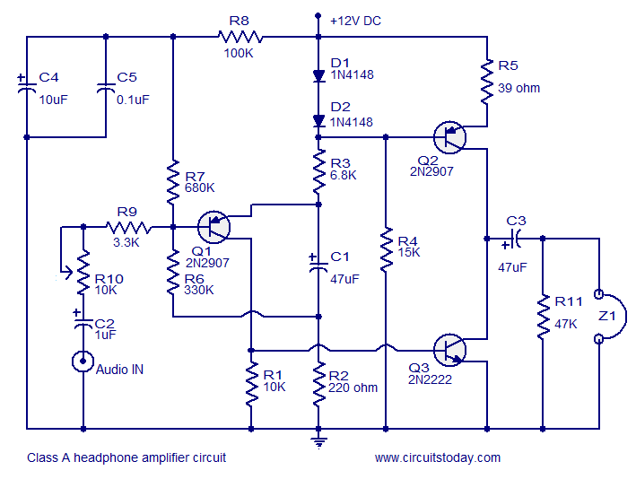
Transistor amplifier circuits that are simple and easy to construct. This includes a headphone amplifier, a four-transistor amplifier, and a low-power amplifier. Transistor amplifier circuits are fundamental components in electronic design, offering various applications ranging from audio amplification to signal...
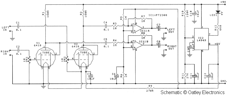
Oatley Electronics, located in New South Wales, Australia, offers several kits based on the Raytheon JAN 6418 sub-miniature valve (tube). The K272A Stereo Tube Preamplifier - Headphone Driver kit, priced at $27 AU, is one such kit. (Note: The...
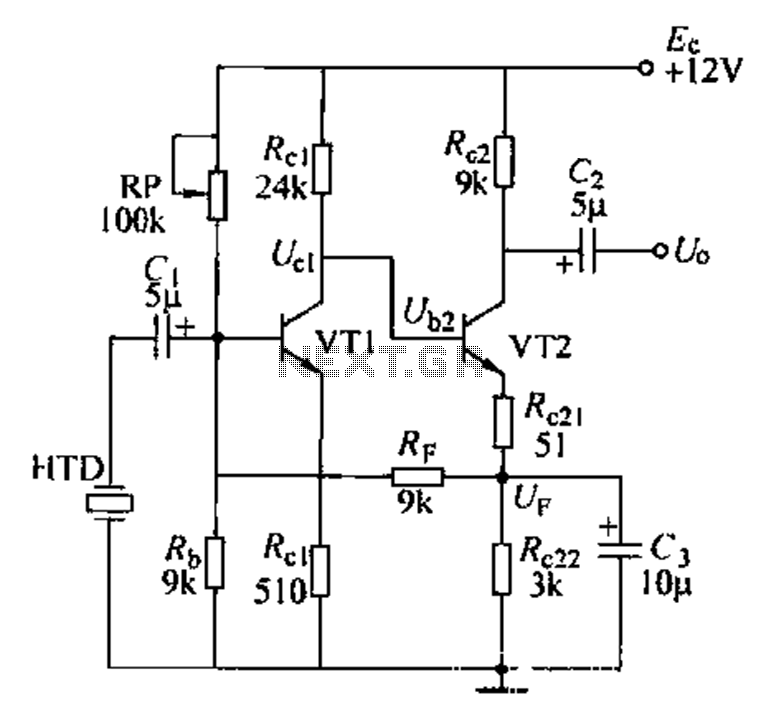
Dctl is a two-stage amplifier, with the first stage amplifying the collector voltage of transistor VT1. The second stage, represented by VT2, is proportional to the current flowing through the winding. The RF signal is applied to the sub-base...