
Simple VHF FM radio
The RF stage is critical for the receiver's performance, and the design leverages the unique properties of transistors and resonant circuits to achieve effective signal processing. The configuration of transistor VT1 as both a common-base and common-emitter circuit is particularly advantageous, as it allows for simultaneous mixing and amplification of the RF signal. The use of a headphone cable as an antenna is a practical solution for compact designs, enabling the reception of VHF signals without the need for bulky antennae.
The audio amplification stages, consisting of transistors VT2 and VT3, are designed to provide sufficient power to drive headphones while maintaining low current consumption, which is essential for battery-operated devices. The careful selection of component values, particularly in the resonant tank circuits and the audio amplifier, ensures that the receiver operates efficiently within the desired frequency ranges.
The adjustment procedures outlined are crucial for optimizing the performance of the receiver. By fine-tuning resistor and capacitor values, the user can achieve the desired operating characteristics, ensuring that the receiver can effectively process FM signals within the specified band. The design's flexibility in component selection, such as the option to replace KT315B transistors with 2N2222, adds to the practicality and accessibility of the circuit for various applications. Overall, this receiver design exemplifies a well-thought-out approach to RF signal processing, combining both functionality and ease of use.The RF stage of the receiver is based on a transistor VT1, this stage works as a mixer and a local oscillator and it works as a synchronous detector. A cable of the headphones works as an antenna. A signal received with this antenna is fed to the input resonant tank circuit L1C2 which is tuned to a center frequency 70 MHz of the VHF band (65.
8. 74. 0 MHz - it`s the first FM band in Russia). From a tap of the coil L1 the RF signal goes to the base of the transistor VT1. The transistor VT1 is configured as a common-base circuit to work as the local oscillator, and in the same time the transistor VT1 is configured as a common-emitter circuit to work as a frequency converter. The local oscillator works in the frequency range of 32. 9. 36. 5 MHz, so the frequency of its second harmonic is within the range of the VHF band 65. 8. 73 MHz. The frequency of the resonant tank L2C5 is two times lower than the frequency of the input resonant tank L1C2, so the conversion occurs at the second harmonic of the local oscillator frequency, and because of this the resulting frequency will be in audio frequency range.
The amplification of the audio frequency provides with the same transistor VT1 which is configured for the audio signals as a common-base circuit (the base is shunted by a capacitor C4). The audio amplifier of the receiver has two stages (VT2, VT3). A preamplifier stage is composed of the transistor VT2, a power amplifier is based on the transistor VT3.
The load of the last stage is the headphones BF1 with resistance of 50 ohms. If the circuit is powered with a 1. 5 volts battery, then the output power is 30 mW at the load of 8 ohms. The current consumption of the circuit is less than 10 mA. The circuit can be mounted in any suitable housing. Coils L1, L2 are wound on a former with a 5 mm outside diameter. The coil L1 has 6 turns of wire of diameter 0. 56 mm (AWG 23), the coil is tapped at the center point. The coil L2 has 20 turns of wire of diameter 0. 56 mm (AWG 23). Coils L3, L3 has 200 turns of wire of diameter 0. 06 mm (AWG 42), they are wound on a ferrite slug of diameter 2 mm, 10 mm long and a permeability of 400. Transistors KT315B can be replaced with 2N2222. The adjustment of the circuit starts with the audio amplifier. Tweak the resistor R6 value to get the current of the transistor VT3 around 6. 9 mA. Tweak the resistor R1 to adjust the operation point of the local oscillator. Tweak the capacitor C6 to adjust the level of the second harmonic of the local oscillator. Adjust the inductance of the coil L2 (by stretching and squeezing the coil) to set up the boundaries of the frequency band.
Adjust capacitor C2 to tune the resonant tank L1C2 to the middle of the VHF FM band. The capacitor C7 is used for tuning. 🔗 External reference
Related Circuits
A sawtooth wave generator circuit using a 555 IC is presented in the article below. The frequency equation is provided with the supply voltage Vcc. The sawtooth wave generator circuit utilizing a 555 timer integrated circuit (IC) is a fundamental...
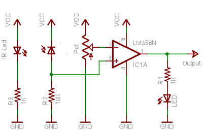
When no light is incident on the diode, it exhibits high impedance (resistance). In contrast, when light strikes the diode, its resistance decreases significantly, approaching a short circuit condition. In the absence of any object in front of the...

Here is the circuit for a simple electronic delay detonator circuit diagram. The overall circuit is implemented in a hybrid IC module. The circuit includes a diode bridge connected to the input terminals, a power supply capacitor connected to...
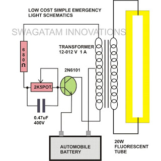
This simple home emergency light circuit utilizes very few components while still being capable of producing a reasonable amount of illumination. The components used are common and can be easily sourced from local electronic retailers. The oscillations induce an...
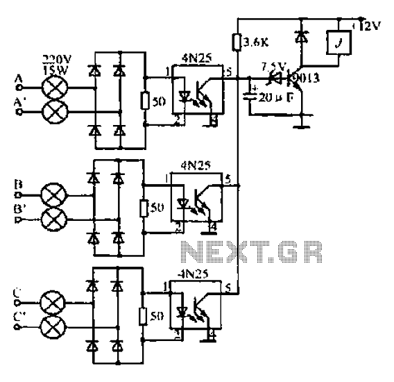
A, B, and C are used for a large power split-phase system. The A + BC range generator phase line features an A-A indole path string containing two 220V/15W bulbs. The bulbs recover based on macro instructions from J...
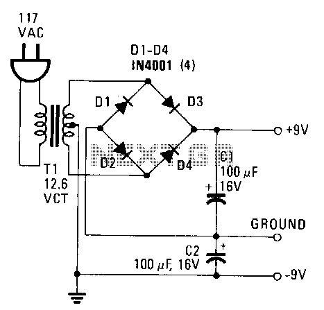
This power supply provides both +9 V and -9 V outputs to replace two 9-V batteries. The rectifier circuit consists of two separate full-wave rectifiers, each connected to the secondary winding of the transformer. The first full-wave rectifier, made...