
VHF Pre-amplifier
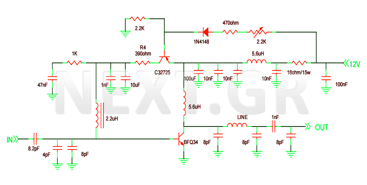
The VHF pre-amplifier circuit utilizing a grounded base configuration is designed to amplify very high-frequency signals while maintaining a low noise figure and high input impedance. This configuration is particularly advantageous for applications in radio frequency (RF) communications, where signal integrity is crucial.
In a grounded base amplifier, the base terminal of the transistor is connected to the ground. This configuration allows for a high-frequency response due to the reduced capacitance effects at the input. The input signal is applied to the emitter, while the collector is connected to the power supply through a load resistor. This arrangement facilitates the amplification of the input signal with minimal distortion.
The circuit typically employs a high-frequency transistor, such as a bipolar junction transistor (BJT) or a field-effect transistor (FET), chosen for its ability to operate effectively at VHF frequencies. The biasing of the transistor is critical to ensure proper operation; therefore, resistors are used to set the operating point, allowing the transistor to remain in the active region during signal amplification.
The output is taken from the collector, and it is often coupled to the next stage of amplification or processing through a coupling capacitor. This capacitor blocks any DC component while allowing the amplified AC signal to pass. Additional components, such as bypass capacitors, may be included to stabilize the power supply and filter out noise, ensuring that the amplified signal remains clean and usable.
Overall, the grounded base configuration in a VHF pre-amplifier circuit is effective for enhancing signal strength while minimizing noise, making it suitable for various RF applications, including television and radio broadcasting, as well as communication systems.Circuit description of a VHF Pre-amplifier using a grounded base configuration 🔗 External reference
Related Circuits
This project involves the construction of a VHF-UHF linear amplifier capable of operating at frequencies ranging from 47 MHz to 740 MHz. It serves as the final output stage for any transmitter functioning within these frequencies. The amplifier utilizes...
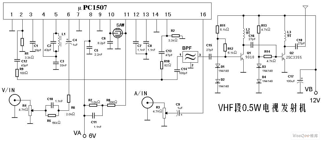
The TV transmitter described here is capable of transmitting audio and video signals from satellite television receivers, VCD players, and video recorders through an open circuit. It can also receive signals using open antennas. This device is ideal for...
The 30-watt amplifier schematic provided below offers a power boost from an input of 4 watts to 6 watts. This circuit is designed to operate within the 88-108 MHz FM broadcast band. It demonstrates stability and delivers a clean...
Tube Tester and Filament Burn-In Jig - This device is designed for prolonged heating of tubes before testing them for insertion into an amplifier. It is crucial to note that the filament generates significant heat, which can raise the...
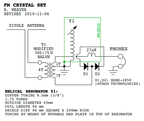
Phase-sensitive detectors typically measure the difference between an input frequency-modulated (FM) signal and the same signal after it has been processed through a resonant circuit or a delay line. A 1N34 diode is suitable for detecting signals at 100...
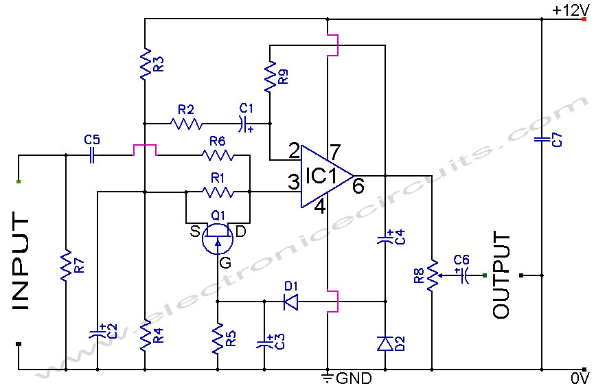
A section of the operational amplifier's output signal is rectified using 1N4148 diodes, followed by filtering, and is then directed to the gate of the FET input shunting circuit. As the output voltage increases, additional input shunting occurs, which...