
VHF Twist-Shift Keying Rotation-Shift Keying Orthogonal BPSK Twist Modulation Motorola SyntorX
The system employs a method for driving the transmitting antenna elements "in quadrature," meaning two precisely synchronized sources of RF energy are offset in phase by 90 degrees. A dual synchronized receiving system is implemented, providing separate paths for the orthogonal signals captured from the receiving antenna. Synchronization necessitates that the injection sources for all mixers in the system are driven from a common source. Additionally, the receiving system must be "normalized," ensuring that the two signal paths are brought back into zero-degree phase synchronicity. The cross-polarized antennas used for feasibility testing consist of two j-pole type elements cut for a resonant frequency of 146 MHz, mounted orthogonally. The transmit antenna was suspended from the rafters of an outbuilding located 50 meters from the shop, where an identical receive antenna was also suspended from the ceiling. The calculated path loss from the transmit end to the receive end was 50 dB. Subsequently, the j-pole elements were incorporated into a cross-polarized Yagi design, with two of these antennas employed to test the system at a 1-mile range. Home-constructed antennas were utilized for these experiments, although the Hy-Gain model 216SAT is noted as a commercially available equivalent.
The output from the signal generator is attenuated using an adjustable attenuator and split into two identical feeds at 0 dBm or lower. Modulation occurs in the Minicircuits SBL-1, which is driven by a bipolar data signal from a pulse generator. The SBL-1 functions as a biphase modulator, capable of either reversing the phase of the RF drive signal or passing it through unaffected, depending on the state of the data signal input introduced into the IF port. A pad in the circuit leg without the SBL-1 is utilized to balance the drive levels, producing a more perfectly circularized radiated signal, typically set to zero attenuation. The antenna drive signals are adjusted for perfect quadrature by trimming the lengths of the antenna drive cables, using an HP 1725, 250 MHz dual-channel oscilloscope, although a 100 MHz oscilloscope is also adequate.
For high-power tests, a modified Motorola SyntorX transmitter operating at 146 MHz serves as the signal source. The modification process for the SyntorX radio to enable 2-meter operation is not extensively covered in this document, but it primarily involves replacing the EPROM in the radio's synthesizer with one programmed for 2-meter frequencies and possibly some retuning. Additional modification information is available from John West, who can provide stock or modified SyntorXs and programmed EPROMs upon inquiry.
The circuit includes a power splitter/attenuator that reduces the drive level to the SCM-1 balanced mixer by approximately 25 dB (the SCM-1 is electrically equivalent to the SBL-1). The phase-modulated output from the mixer is amplified by about 25 dB and delivered to the RF OUT 1 jack, while a non-modulated output is also provided.The material in this section shows how we built the Twist-Shift system for VHF using commonly available (and cheap) surplus land mobile VHF transceivers modified to operate on the 2-meter ham band. The radios we used were the 100-watt Motorola SyntorX model. The radios were additionally modified for the Twist-Shift experiments as described below. This section also describes the auxiliary circuitry needed to implement the system and the test setup for the experiments we ran to prove that the concept works and to quantify just how well it works. This page describes the VHF Twist-Shift Keying setup using the SyntorX radios. The material is presented, not as a hard and fast specification of equipment and circuitry, but as an example of how Twist-Shift can be implemented.
A method for driving the transmitting antenna elements `in quadrature`, that is, with two precisely synchronized sources of RF energy offset in phase by 90 degrees. A dual synchronized receiving system that provides separate paths for the orthogonal signals picked off from the receiving antenna.
Synchronization requires that injection sources for all mixers in the system be driven from a common source. The receiving system must also be "normalized", that is, the two signal paths must be brought back into zero-degree phase synchronicity.
The cross-polarized antennas we used for feasability testing are shown here. They consist simply of two j-pole type elements cut for a resonant frequency of 146 MHz mounted orthogonally. The transmit antenna was suspended from the rafters of an outbuilding on my property 50 meters distant from my shop where an identical receive antenna was likewise suspended from the ceiling.
Calculated path loss from the transmit end to the receive end was 50 dB. Later, the j-pole elements were incorporated into a cross-polarized yagi design. Two of these antennas were used to check the system at 1 mile range. [We used home-constructed antennas for our experiments. The Hy-Gain model 216SAT would appear to be an equivalent, commercially available alternative to our antennas. ] The output from the signal generator is reduced in level by the adjustable attenuator and split into two identical feeds at 0 dBm or less.
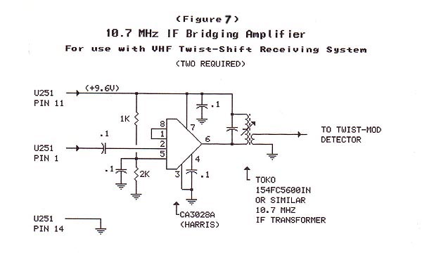
Modulation takes place in the Minicircuits SBL-1 driven by a bipolar data signal from a pulse generator. The SBL-1 serves to either 1) reverse the phase of the RF drive signal through the device, or 2) NOT reverse the drive signal (pass it through un-affected).
The state of the data signal input, introduced into the IF port, determines whether the RF signal is reversed or not. In other words the SBL-1 is a biphase modulator. The pad shown in the leg of the circuit without the SBL-1 is used to balance the drive levels so as to produce a more perfectly circularized radiated signal.
Normally the setting of that attenuator is zero. The antenna drive signals were adjusted for perfect quadrature by trimming the antenna drive cable lengths using an HP 1725, 250 MHz dual-channel oscilloscope. (A good 100 MHz scope will work also. ) We used a Motorola SyntorX transmitter, modified for operation on 146 MHz, as the signal source for our high-power tests.
Modification of the Syntor X radio for 2-meter operation is beyond the scope of this article, but it`s not terribly hard to do. The modification consists mainly of replacing the EPROM in the radio`s synthesizer with one programmed for 2-meter frequencies, and maybe some retuning.
Here`s some mod info John West put together. [John can also provide stock or modified-for-2-meter SyntorXs and programmed EPROMs. Inquire The circuit consists of a power splitter/attenuator that reduces the drive level to the SCM-1 balanced mixer by about 25 dB (the SCM-1 is electrically equivalent to the SBL-1). The phase modulated output from the mixer is then amplified about 25 dB and delivered to the RF OUT 1 jack.
A non-modulated output is delivered to the 🔗 External reference
Related Circuits
Tube Tester and Filament Burn-In Jig - This device is designed for prolonged heating of tubes before testing them for insertion into an amplifier. It is crucial to note that the filament generates significant heat, which can raise the...
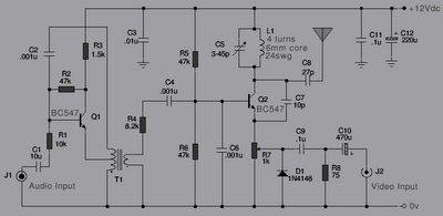
The following is a series of simple TV transmitters utilizing negative sound modulation and PAL video modulation. This design is suitable for countries employing TV systems B and G. Inductor L1 can be constructed using 24 SWG wire, consisting...

The TLE6282G is an H-Bridge and Half Bridge Driver IC designed for high-current DC brush motor applications in PWM control mode. It is suitable for use in injector and valve applications across 12V, 24V, and 42V power networks. This...
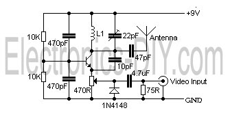
This is a simple video transmitter capable of transmitting signals up to 50 meters. It can be connected to a camera or other video sources, allowing viewing on a VHF channel analog TV. The transmitter operates on a supply...

The 30-watt amplifier circuit provides a suitable power boost from an input of 4 watts up to 6 watts. It is designed to operate within the 88-108 MHz FM broadcast band and maintains stability while delivering a clean output...
The 555 timer oscillator section can be removed and replaced with a preferred microphone modulating circuit to transmit audio to a television set, requiring minimal tuning. The schematics available on Schematics Depot were sourced from the internet and are...
Warning: include(partials/cookie-banner.php): Failed to open stream: Permission denied in /var/www/html/nextgr/view-circuit.php on line 713
Warning: include(): Failed opening 'partials/cookie-banner.php' for inclusion (include_path='.:/usr/share/php') in /var/www/html/nextgr/view-circuit.php on line 713