
VHF Beacon
The circuit modification involves taking out the 555 timer oscillator, which is typically used for generating pulse-width modulation signals, and integrating a microphone modulating circuit instead. This modification allows for the transmission of audio signals, such as voice, directly to a television set.
To implement this, a suitable microphone circuit must be selected that can effectively convert sound waves into an electrical signal. Common choices include electret condenser microphones or dynamic microphones, which can be configured to work with a preamplifier to boost the signal strength before modulation.
The microphone output needs to be modulated to ensure compatibility with the transmission requirements of the television set, which may involve amplitude modulation (AM) or frequency modulation (FM) techniques. The choice of modulation will depend on the specific characteristics of the television's audio input.
Once the microphone circuit is integrated, the overall circuit will require tuning. This tuning process may involve adjusting the gain of the microphone preamp, selecting appropriate filter components to eliminate noise, and ensuring the modulation frequency aligns with the television's audio input specifications.
In conclusion, by replacing the 555 timer oscillator with a microphone modulating circuit, it is possible to create a system that facilitates audio transmission to a television set. Careful selection of components and tuning will enhance the performance and clarity of the transmitted audio.You can cut away the 555 timer oscillator part and add your favorite microphone modulating circuit to transmit voice over to your tv set with a little tuning. Schematics in Schematics Depot were found on the internet and assumed to be in public domain. Contact webmaster if the copyright holder wants them pulled for any reason. 🔗 External reference
Related Circuits

The amplifier utilizes a single MRF245 transistor and delivers 80 W of output power with a gain of 9.4 dB across the frequency range of 143 to 156 MHz. The circuit design for the amplifier featuring the MRF245 transistor is...
Radio-frequency schematics (also see NE602 datasheet and application note). This page contains electronic circuits related to RF receivers. This index features a broad collection of RF receiver circuits. Radio-frequency (RF) schematics are essential for designing and implementing circuits that operate...
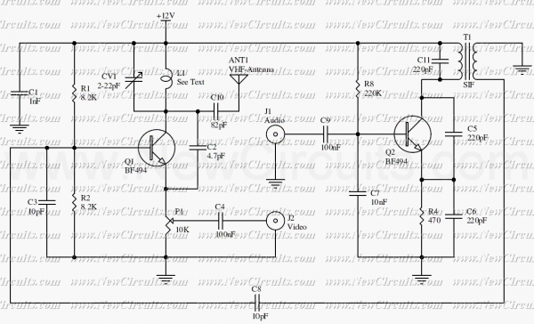
The circuit presented here is a simple audio/video transmitter with a range of 3 to 5 metres. The A/V signal source for the circuit may be a VCR, a satellite receiver or a video game etc. A mixer which...
Once again my collection of projects creation has been interrupted by another necessity. Patrick and other people have asked me for a circuit of a VHF power amplifier. These circuits are my "standard" building blocks that can be used...
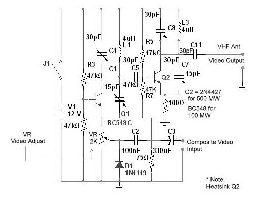
Tuned circuits consist of C4, L1, C8, L3, and two 15 pF trimmer capacitors positioned across the collectors and emitters of both transistors. Other NPN transistors such as BC54, 2N3642, and 2N3643 may also be suitable. The circuit is...
The intelligent discussion of VHF systems necessitates an understanding of how VHF energy propagates through a system. At VHF frequencies, the wavelength is relatively short, calculated as F/983, where F is the frequency in MHz. For example, a typical...
Warning: include(partials/cookie-banner.php): Failed to open stream: Permission denied in /var/www/html/nextgr/view-circuit.php on line 713
Warning: include(): Failed opening 'partials/cookie-banner.php' for inclusion (include_path='.:/usr/share/php') in /var/www/html/nextgr/view-circuit.php on line 713