
VHF/UHF TV modulator
The TV modulator operates primarily as a low-power transmitter designed to convert video signals into radio frequency (RF) signals suitable for transmission to standard television receivers. The core of the modulator consists of a modulatable crystal oscillator, which is responsible for generating a stable carrier frequency. In this design, the oscillator operates at 27 MHz, a frequency that allows for the use of readily available and cost-effective crystal components.
The modulated output from the oscillator is then processed by a harmonics generator, which expands the frequency spectrum of the signal. This generator produces harmonics of the original 27 MHz signal, effectively creating a series of peaks across a broad frequency range, extending up to approximately 1800 MHz. This ensures that the output signal encompasses multiple television broadcast bands, including VHF channels 2-4 (band I), VHF channels 5-12 (band III), and UHF channels 21-69 (bands IV and V).
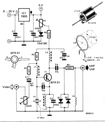
The design utilizes a compact printed circuit board (PCB) to facilitate assembly and minimize complexity. The PCB is single-sided, which simplifies the manufacturing process and allows for easier assembly by users who may wish to construct the modulator from scratch. The components are mounted directly onto the PCB, with particular attention paid to the inductors. Coils L1 and L2 are created by winding 3.5 turns of 0.2 mm thick enamelled copper wire around a 3.5 mm ferrite bead, while inductor L4 is formed with a single turn of thicker copper wire (0.8-1 mm) wound in air with an 8 mm diameter. Inductor L3 is commercially available and can be sourced from electronic component suppliers.
The crystal oscillator requires a third overtone crystal with a frequency between 25 MHz and 30 MHz, broadening the options for component selection. The circuit's performance is contingent upon the use of suitable Schottky diodes (D1 and D2), which are essential for the modulation process. While specific types are suggested, any UHF Schottky diode that meets the necessary specifications can be utilized, providing flexibility in sourcing.
In summary, the TV modulator serves as an efficient means of transmitting video signals over the airwaves by modulating a stable carrier frequency, generating a spectrum of frequencies that align with standard television channels, and employing a straightforward PCB design for ease of construction and assembly.A 'TV modulator' is really no more than a transmitter. It is a very small transmitter, admittedly, but none the less that is what it is. What does a modulator actually do? In general -and this design is no exception to the rule - it is a simple oscillator that generates a frequency somewhere in the VHF or UHF region. The oscillator is modulated with the video signal and the modulated carrier wave thus generated is fed into the TV set's aerial input via a cable.
Then all that remains to do is tune the TV to the correct frequency. The block diagram of figure I shows how this is achieved. The TV modulator is made up of two parts, namely a modulatable crystal oscillator and a harmonics generator. The oscillator operates at a frequency of 27 MHz, which is quite low so inexpensive crystals are readily available.
The harmonics generator converts the oscillator signal into a sort of frequency spectrum containing all the multiples of 27 MHz up to about 1800 MHz. The TV modulator's output signal is made up of a large number of little peaks, each of which is a complete transmitter signal.
At least one of these will always be in band I (VHF channels 2. . . 4), one in band III (VHF channels S. . .12) and many of them will be in bands IV and V (UHF channels 21.. .69). The tiny printed circuit board designed for this circuit is shown in figure 3. It is not double-sided as this was found to be unnecessary. Construction is thereby simplified and readers who do not buy the board through our EPS service (tut-tut) will find it easier to make themselves. Building the circuit is simply a matter of fitting the components onto the printed circuit board. The coils, often a source of much teeth-gnashing and hair-pulling, will not be a problem in this case.
Two of them, Ll and L2, are made by winding 3.5 turns of enamelled copper wire (about 0.2 mm thick) on a 3.5 mm ferrite bead. Another, L4, is just one turn of copper wire (0.8. . . 1 mm thick) air-wound with a diameter of 8 mm. The fourth inductor, L3, can simply be bought. Any third overtone crystal with a frequency of between 25 and 30 MHz will work in this circuit. A number of suitable values are advertised in this issue. The only parts that might prove difficult to find are diodes Dl and D2. The ones stated in the parts list are available at the moment but do not give up hope if your corner shop does not have them.
The only important thing is that they must be UHF Schottky diodes; the actual type number is of little consequence. 🔗 External reference
Related Circuits
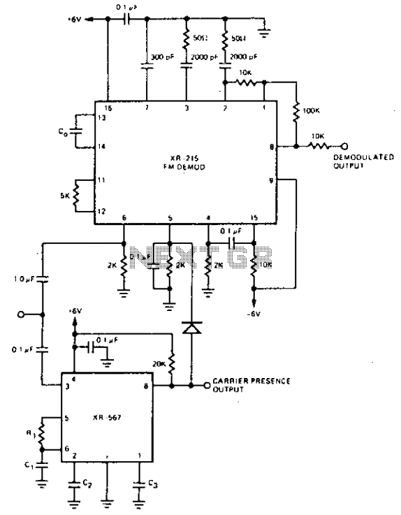
For FM demodulation applications where the bandwidth is less than 10% of the carrier frequency, an XR-J567 can be used to detect the presence of the carrier signal. The output of the XR-567 is used to turn off the...
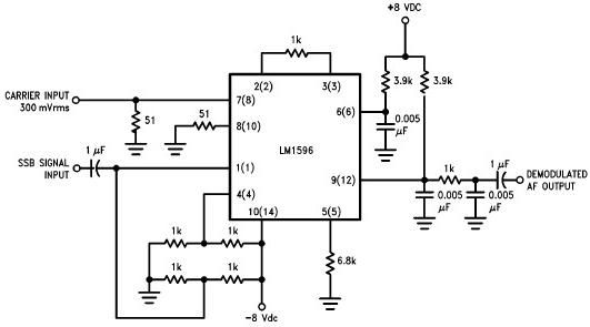
A simple single sideband (SSB) suppressed carrier demodulator circuit can be constructed using the LM1596 balanced modulator-demodulator integrated circuit (IC). The carrier signal should be applied to the carrier input port at an optimal level of 300 mVrms to...
A simple, low component count phase locked loop that locks onto and detects the amplitude of an incoming baseband 7 bit Barker code using a switched resistor demodulator that is driven directly by a microcontroller's output pins. Balanced modulators...
More: An electronic schematic is a representation of the components and connections within an electronic circuit. It serves as a blueprint for constructing electronic devices, allowing engineers and technicians to visualize how components interact and function together. The schematic...
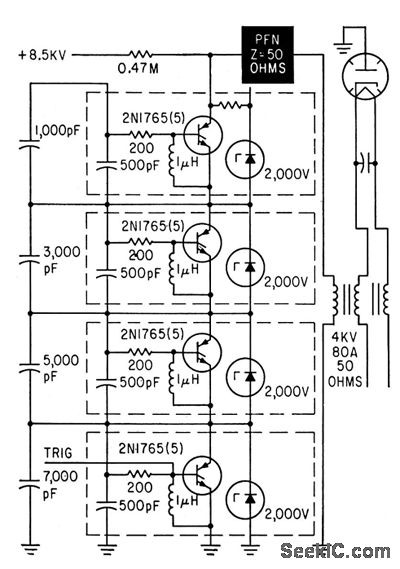
A trigger is applied to the first of four 2-kV switch modules arranged in series, enabling simultaneous triggering of the other modules to deliver a 16-kV, 20-amp pulse to a type 7208 Ku-band coaxial magnetron through a standard 50-ohm...
A Phase Locked Loop (PLL) can be utilized to create a Frequency Modulation (FM) demodulator. The PLL circuit tracks the input frequency by adjusting the voltage input of a Voltage-Controlled Oscillator (VCO). The Phase Locked Loop (PLL) is a critical...