
PLL FM Demodulator

The Phase Locked Loop (PLL) is a critical component in many electronic systems, particularly in communication applications where frequency stability and accuracy are paramount. In the context of an FM demodulator, the PLL operates by continuously adjusting the output frequency of a Voltage-Controlled Oscillator (VCO) to match the frequency of an incoming FM signal.
The basic structure of a PLL consists of three main components: a phase detector, a low-pass filter, and a VCO. The phase detector compares the phase of the incoming FM signal with the phase of the VCO output. When a phase difference is detected, the phase detector generates an error signal that reflects this difference. This error signal is then filtered by the low-pass filter to remove high-frequency noise, resulting in a smooth control voltage that is fed into the VCO.
The VCO then adjusts its output frequency based on this control voltage, effectively locking onto the frequency of the incoming FM signal. The feedback loop continues to operate, maintaining the phase alignment between the PLL output and the input signal. This process allows for accurate demodulation of the frequency-modulated signal, enabling the extraction of the original audio or data information encoded within the FM wave.
For implementation, careful selection of the components, including the VCO and phase detector, is crucial to ensure optimal performance. The PLL design must also consider factors such as loop bandwidth and stability to prevent issues like phase jitter or loss of lock. Overall, the PLL serves as a robust solution for FM demodulation, offering a reliable means of converting frequency variations back into the original signal.PLL (Phase Locked Loop) can be used to make a FM demodulator. PLL circuit track the input frequency by controlling a voltage input of a VCO (Voltage-Controlled.. 🔗 External reference
Related Circuits
The CF5019 series are high-frequency, third overtone crystal oscillator module ICs. They integrate an oscillator circuit and an output buffer that function at high frequencies on a single chip. The oscillator circuit utilizes CMOS inverters and a built-in damping...
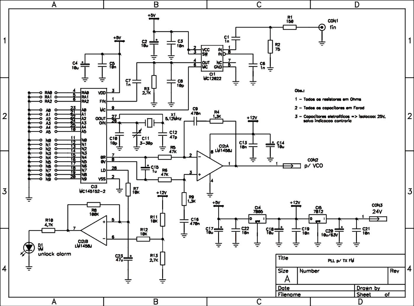
This is a schematic of a synthesized Phase-Locked Loop (PLL) for a low-power FM transmitter. It can also be utilized with other circuits, provided that the loop filter response, components, VCO tank circuit, and appropriate thumbswitch programming keys and...
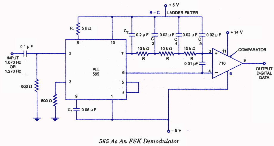
A highly effective application of the 565 Phase-Locked Loop (PLL) is its use as a Frequency Shift Keying (FSK) demodulator. In the 565 PLL, frequency shifting is typically achieved by driving a Voltage-Controlled Oscillator (VCO) with a binary data...
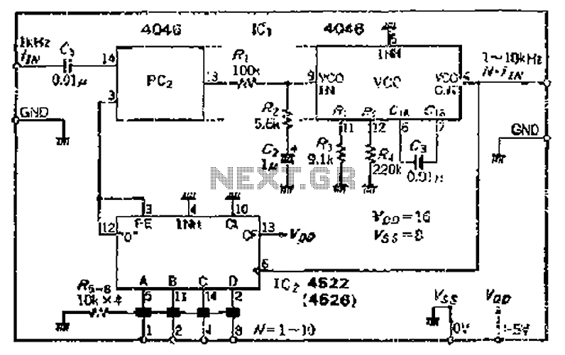
The CMOS IC 4046 Phase-Locked Loop (PLL) operates with a maximum frequency of 1 MHz. It is connected to a programmable divider, allowing it to process input frequencies. As the frequency increases by a factor of t, the circuit's...
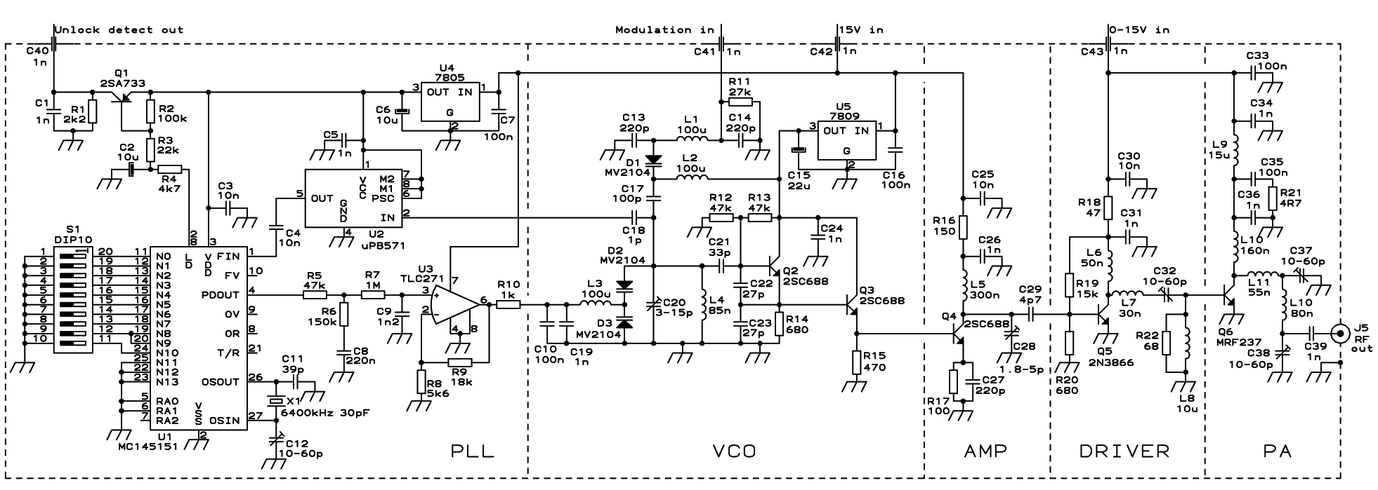
The PLL transmitter exciter is designed to provide a stable, low noise, frequency-selectable RF signal, which is amplified to a controllable output power sufficient to drive a power amplifier. It utilizes a PLL frequency synthesizer based on the MC145151,...
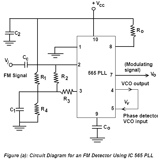
Phase Lock Loop (PLL) FM Detector with 565 PLL IC. The circuit diagram and internal structure of the PLL IC 565 are shown in the given figures. The Phase Lock Loop (PLL) FM Detector utilizing the 565 PLL IC is...