
Video Preamp Circuit

The NE592 and LM733 are operational amplifiers specifically designed for high-frequency applications, making them suitable for video amplification tasks. The configuration of J2 and J3 allows for differential output signals, which can be advantageous in applications requiring noise cancellation or improved signal integrity. The anti-phase outputs can be further processed or utilized in differential signaling environments.
R2, serving as a gain control resistor, plays a critical role in adjusting the amplification factor of the video signal. By varying the resistance value of R2, the gain can be fine-tuned to meet the requirements of the specific application, ensuring optimal signal quality and preventing distortion.
The bandwidth of approximately 100 MHz indicates that this amplifier can handle a wide range of video frequencies, making it suitable for both standard and high-definition video signals. This characteristic is essential in ensuring that the amplifier can accurately reproduce the fast-changing signals typically found in video applications without introducing significant phase shifts or attenuation.
In summary, this schematic effectively employs the NE592 or LM733 to achieve high-performance video amplification with adjustable gain and differential output capabilities, suitable for a variety of video processing applications. An NE592 or LM733 is used as a general-purpose video amplifier in this schematic. J2 and J3 provide two anti-phase outputs. R2 is a gain control. The bandwidth is about 100 MHz.
Related Circuits
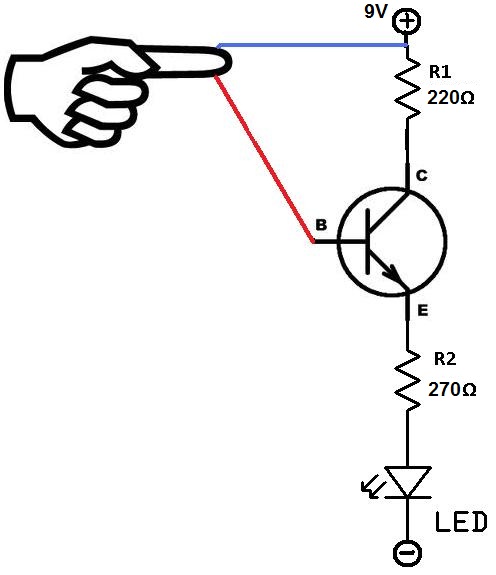
This project utilizes two wires, one red and one blue, which function as touch sensor wires. When a person touches both wires, the circuit closes, allowing current to flow and illuminate the LED. A 9-volt battery or an external...
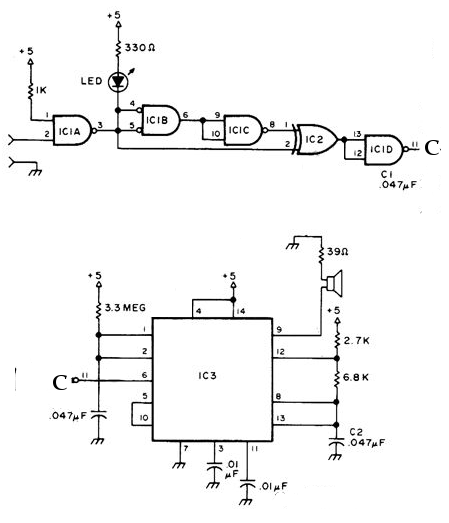
All sound effects are generated internally by the HT2884 integrated circuit (IC). The device operates on a 3-volt battery but is compatible with any voltage ranging from 2.5 to 5 volts. Switch S1 functions as the on/off switch. The...

The IR Theremin hardware schematic is notably simple, as the primary input and output devices require minimal connections. This simplicity can be a double-edged sword, as fewer hardware components often lead to increased software complexity. The main components utilized...
This universal power supply includes a bridge rectifier, a voltage stabilizer (78xx), and a PNP power transistor. This combination allows for a load current output. The universal power supply circuit is designed to convert alternating current (AC) from the mains...
The NE556 timer can function as an indicator for the static state of a digital logic audible terminal. An audible logic probe is beneficial for visually inspecting a component while simultaneously checking the logic state at another point far...

The following circuit illustrates a simple 100W inverter circuit diagram. This circuit is based on the CD4047 integrated circuit (IC). Features include low power CMOS technology. The simple 100W inverter circuit utilizes the CD4047 IC, which is a versatile device...