
video sequencer using analog multiplexers
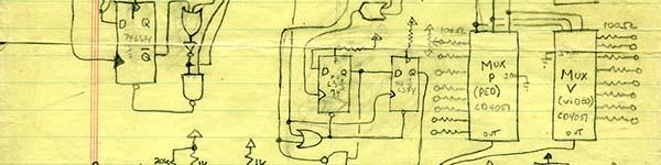
The circuit design utilizes two CD4051 multiplexers to facilitate the selection of video inputs, enabling the user to switch between multiple sources seamlessly. The CD4051 is a CMOS analog multiplexer/demultiplexer that allows for the routing of analog signals based on binary control inputs. By connecting the outputs of the CD4051s to the video processing circuitry, the sequencer can effectively manage the flow of video signals. The integration of the CMOS 74C922 key encoder allows for user-friendly operation, enabling manual selection of video sources through momentary switches.
The sequencer's architecture is designed to accommodate both analog and digital signals, providing versatility in various applications. The inclusion of pedestal controls for each channel enhances the functionality of the sequencer, allowing for precise adjustments of video levels. The ability to operate as a control voltage source adds another layer of utility, enabling the sequencer to be used in audio applications as well.
In terms of signal integrity, the design emphasizes minimizing visual artifacts during switching operations. The vertical interval switching feature is crucial for maintaining the quality of the output signal, particularly in professional settings where visual fidelity is paramount. The sequencer's design also allows for creative applications, such as generating rhythmic patterns and effects in live performances, making it a valuable tool for artists and engineers alike. Overall, this sequencer exemplifies a practical application of multiplexer technology in video and audio signal processing, showcasing the potential for innovative designs in electronic engineering.Here is another example of using a CD4051 multiplexer, or more accurately a pair of CD4051s in parallel. I had lifted much of the core logic and circuits from Dave Jones designs. Again these are old designs offered from a historical perspective. I built this sequencer for a public access facility I was involved with for a while. At the time they o nly had a black and white switcher. I built this sequencer in a box along with a Dave Jones color sync generator, a simple oscillator, and a Dave Jones output amp. Though this sequencer has a sync insertion section in the final stage that removes the color burst, using it with an output amplifier, which reinserts color burst, allowed the members of the group to use this as a color switcher for studio shoots, and as a sequencer.
A video sequencer is a processor that will sequentially cut between some number of inputs according to a clock. Commercially they are popular in security settings where a single monitor would switch between multiple security cameras.
Artists have used them for real time cutting between multiple sources of imagery, either camera sources, or outputs of other modules. You can use a sequencer to create a live wiggle 3D effect with two or more cameras, as well as patch irregular clock signals to move rhythmically between multiple versions of a patch.
The sequencer I have in my modular synth, and a similar one built for the Experimental Television Center, had two additional modes to determine switching between between sources. In the binary mode, instead of just a single clock input (oscillator), there are three switches, and jacks, to define a 3 bit binary word that in turn determines which of the eight channels is on.
Using the three jacks instead of the switches means you can use three oscillators to determine the switching. This will seem to randomize, or create an irregular order and rhythm to the sequence. I can also feed comparator outputs into the three binary inputs, potentially using three mattes to layer eight sources (or two comparators to layer 4 sources.
). Pedestal controls for each channel allows for adjusting the black levels of the video sources, but using a +-5 volt output for the sequencer, you can also use the sequencer as a control voltage source, using the pedestals without video sources. When built with pedestals that have voltage control inputs, you can use this to cut between sound sources in real time.
This is a simple eight channel sequencer; it can take up to eight video inputs. It has no second level control, nor is there a binary mode. It does, however, include a CMOS 74C922 key encoder to encode eight momentary switches used to select a source, not unlike a bus on a traditional switcher. The selected channel will either output (switcher mode), or determine which channel the sequencer will count up to before going back to channel 1 (sequencer mode).
The front panel has a mode switch for switcher/sequencer, and a switch here labeled VIS, which stands for vertical interval switching. When VIS is on, in the sequencer mode, the sequence rate will go no faster than vertical, and the switching from the oscillator will occur during the vertical interval, preventing any visual glitches.
You would need to turn VIS off to see bars when you increase the oscillator beyond field rate. When in switcher mode, the DA output from the C922 is routed through a NAND gate to the load input of the LS161 (a synchronous 4 bit binary counter). That will make the LS161 counter load the keyed channel, also fed from the C922 to the counter. The low true on the load input copies the LS161 input to the output. The LS161 counts up in binary upon receiving each clock pulse. The LS161 will count up to the binary word at the input of the LS161 as the 74LS85 compares the input and output of the counter.
When the output of the counter is greater than or equal to the input of the counter, the Q output of the f 🔗 External reference
Related Circuits
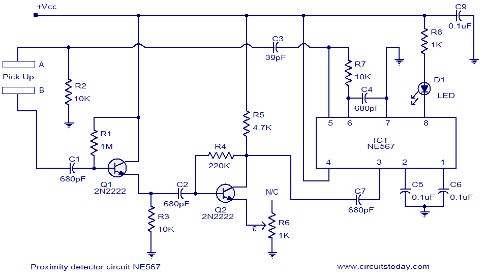
A simple proximity detector circuit utilizing the NE567 integrated circuit (IC). The circuit activates an LED when an object approaches the sensor. The NE567 is a versatile phase-locked loop (PLL) device commonly used for applications such as proximity detection due...
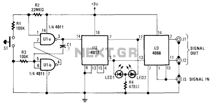
The A/B switch circuit comprises three integrated circuits (ICs) and several resistors. Two gates from a 4011 quad 2-input NAND gate (U1A and U1B) are configured as a monostable multivibrator. When switch SI is activated, it triggers a 4017...
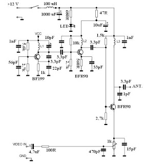
This video transmitter circuit operates on the UHF channel frequency of 470-580 MHz, specifically channels 21-34. It can transmit video signals over distances ranging from 30 to 100 meters when using a cable length of 10 to 20 cm....
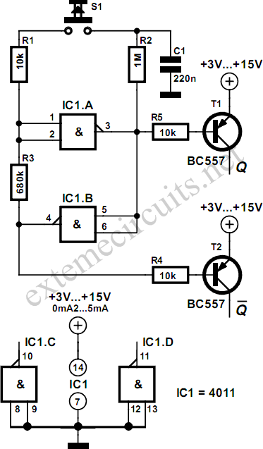
Using just two NAND or inverter gates, it is possible to build a D-type (or toggle) flip-flop with a push-button input. At power-up, the output of gate N2 is at a logical 1, ensuring that transistor T2 is switched...
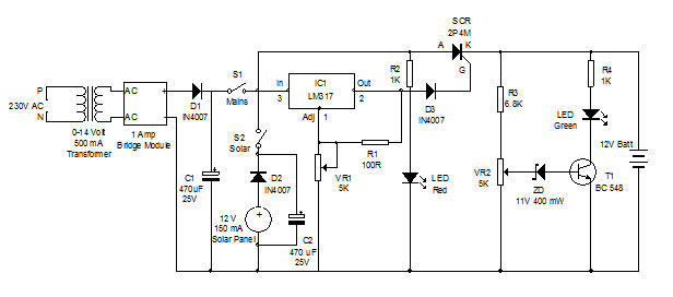
Battery charger utilizing solar and electrical power with a circuit diagram. This dual power source battery charger can charge a lead-acid battery using two different power sources. The battery charger circuit is designed to efficiently charge a lead-acid battery by...
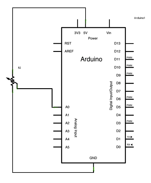
A potentiometer is a simple knob that provides variable resistance, which can be read into the Arduino board as an analog value. In this example, a potentiometer is connected to one of the Arduino's analog inputs to control the...
Warning: include(partials/cookie-banner.php): Failed to open stream: Permission denied in /var/www/html/nextgr/view-circuit.php on line 713
Warning: include(): Failed opening 'partials/cookie-banner.php' for inclusion (include_path='.:/usr/share/php') in /var/www/html/nextgr/view-circuit.php on line 713