
Vincent Motorcycle Electrics
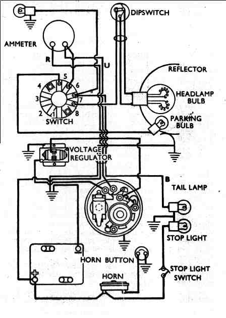
The redundant closed-loop ground wiring system is a critical component in ensuring the reliability of the electrical system in the charging circuit. By employing a closed-loop design, the system enhances the grounding effectiveness, reducing the potential for ground faults that could compromise the performance of the electrical components. The schematic illustrates the integration of the Alton generator with the rectifier/regulator, highlighting the importance of proper grounding to maintain system integrity.
The choice of components, such as the Podtronics unit, suggests a move towards more reliable alternatives in response to the failure of the original Alton regulator. The noted 23mA leakage through the voltage regulator's ground lead is significant, indicating that even minor currents can lead to battery depletion, which emphasizes the need for effective circuit management strategies. The recommendation to add a switch to interrupt the current flow during periods of inactivity is a practical solution, allowing users to preserve battery life without the need for frequent disconnection.
Further, the explanation of the operational principles of voltage regulators provides insight into the design challenges faced in maintaining a balance between performance and efficiency. The necessity for isolation of the battery from the generator's armature when not in motion is a key operational requirement, ensuring that the battery is not subjected to unnecessary loads that could lead to premature failure. The discussion on the use of mechanical versus solid-state regulators illustrates the evolution of technology in this field, with each type offering distinct advantages and drawbacks.
In summary, the careful consideration of component selection, circuit design, and operational protocols is essential in creating a robust electrical system for motorcycles. The integration of effective grounding solutions and the management of leakage currents are vital in enhancing overall system performance and reliability.This diagram shows a redundant - closed loop ground wiring system. This is intended to reduce dependency on the frame for ground purposes in the charging circuit. The second (lower) diagram is as the bike was built using the 12 volt Alton generator and an Alton supplied rectifier/regulator. It is a bare bones diagram. Within 2 years, the Alton supplied rectifier/regulator failed, and Paul Hamon recommended using a replacement. I selected a Podtronics unit as installed in the upper diagram I installed the Alton unit and I find there is a 23mA bleed to ground through the voltage regulator green ground lead. The Vincent 12v battery was running down when simply sitting and the fault traced to this. What is my problem Craig Comontofski 11/7/2011 On the wiring diagram ("magneto" type) we suggest to add a switch to avoid a small leak current passing through the small black wire of rectifying regulator when the bike is at rest.
This is approximately 20 milliamps. Not very high but enough to drain a battery in a couple of days (depending on the battery range). So add this switch if you want to avoid this problem. Another solution is to remove the fuse as soon as your bike is at rest for more than a couple of days. Or alternatively to use a home battery charger for long rests. This inconvenience comes from the source of rectifying-regulators. They actually come from small capacity Japanese motorcycles on which the ignition key switches the small black wire of rectifying-regulator (as indicated on the other diagram).
In this case no leaking current because the battery is disconnected from the rectifying-regulator when the bike is at rest (ignition off). If you start the bike without switching "on" and run the generator with "open" circuit, it is not so good for both generator and rectifying-regulator if you insist for all trip but it won`t destroy them for just a couple of minutes running this way.
By the way if you do so you surely can hear the generator "rumbling" and of course the needle of ammeter won`t move at all. Paul Hamon 11/8/2011 Voltage regulators for DC generators have a requirement to isolate the battery from the generator`s armature when the armature is not rotating.
Failure to do so would put a load of around 1/2 Ohm (the resistance of the armature winding) on the battery. Mechanical regulators use a relay. Leakage of relays is so low measuring it would be counting single electrons. Solid state regulators typically use a diode. All diodes have a leakage current specification. The leakage can be measured without substantial heroics which is to say it is in the milliampere to microampere range.
Solid state regulators for alternators use Zenor diodes to turn thyristors (SCRs) on. SCRs are just three of four (depending on how you like to count them) diodes in a fancy configuration. But we are back to diodes, things that leak. The diode can be specified to minimize leakage but at the price of compromising another specification.
The design of a regulator (and just about anything else more complicated than a paper clip) is an exercise in compromise. There is no Utopia. Sorry, limitations of available technology. Doug Wood 11/9/2011 12 volt LED 7" headlight: NGK B6ES spark plug equivalents: NGK 7432, Accel 143, AC Delco 43XL, Autolite 2616, Beck Arnley 176-5002, Bosch W8CC, Cham
🔗 External reference
Related Circuits
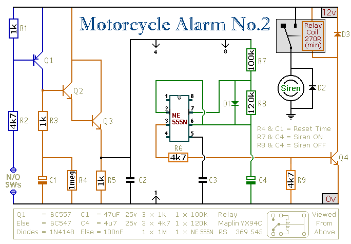
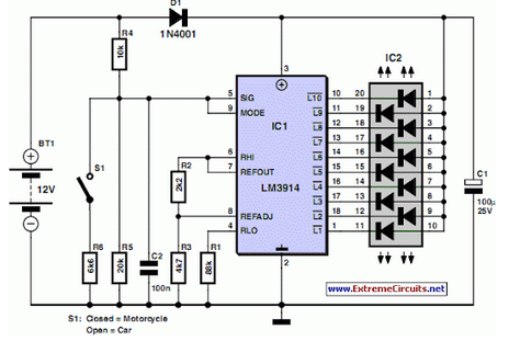
This circuit features an intermittent siren output and automatic reset. It can be operated manually using a key switch or a hidden switch; however, it can also be wired to activate automatically when the ignition is turned off. By...
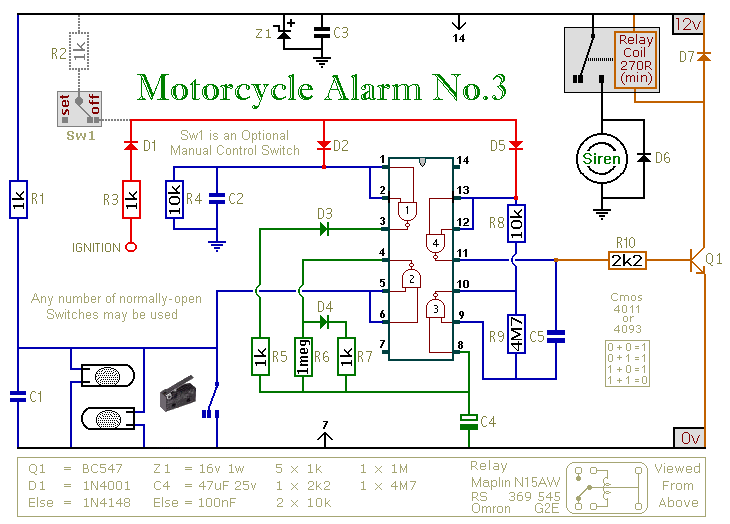
This circuit provides an intermittent siren output with an automatic reset feature. It can be operated manually through a key-switch or a hidden switch, and it can also be configured to activate automatically when the ignition is turned off....
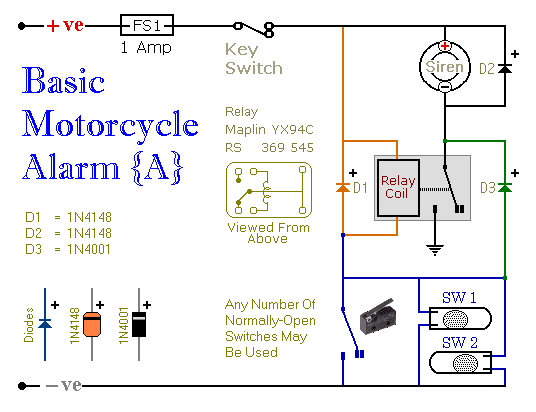
These are two easy-to-build relay-based alarms that can be used to protect motorcycles, among other applications. Using relays with 6-volt coils will safeguard a "Classic Bike." Both alarms are compact, with completed boards occupying approximately half a cubic inch...
Camping today often requires bringing various electronic devices for daily activities or entertainment. Frequently, a charge is needed for these devices. In modern camping scenarios, the reliance on electronic devices has significantly increased. Campers typically bring smartphones, tablets, GPS devices,...
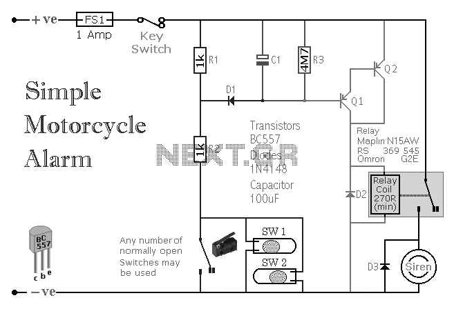
A simple transistor-based motorcycle alarm circuit. This circuit is easy to build and designed to operate at 12 volts. However, by replacing the relay with one that has a 6-volt coil, it can also provide protection at that voltage. The...
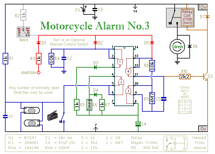
This circuit features an intermittent siren output and automatic reset. It can be operated manually using a key-switch or a hidden switch; but it can also be wired to set itself automatically when you turn off the ignition. By...