
Motorcycle Alarm Number 2
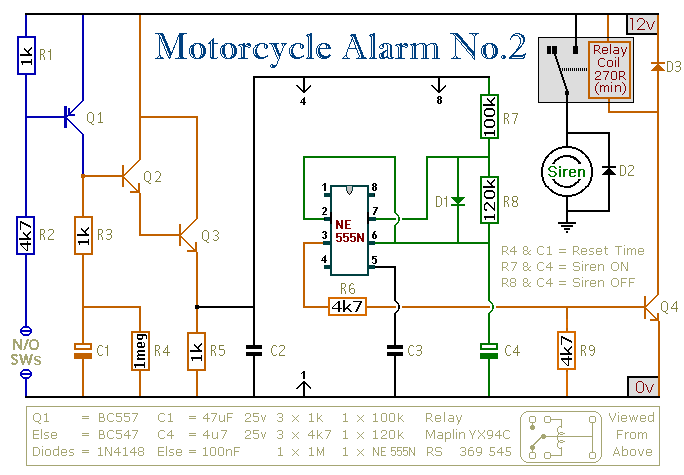
This circuit design incorporates an intermittent siren output with an automatic reset feature, enhancing the security of the motorcycle. The system can be activated through manual control or automatically triggered by the ignition state. The inclusion of external relays allows for versatile applications, such as immobilizing the bike and controlling auxiliary functions like lighting.
The integration of multiple normally-open switches enhances the system's responsiveness to various conditions, such as movement or tampering. The use of tilt switches and micro-switches adds layers of protection for critical components and areas prone to unauthorized access. The timing of the siren activation is adjustable, allowing customization based on user preference and environmental factors.
The design emphasizes the importance of using an electronic siren to avoid detection and tampering, while also providing flexibility in terms of power management through the relay system. The circuit board layout is optimized for reliability, with careful consideration given to component placement and protection against moisture.
The detailed support materials provided with the system ensure that users have the necessary resources to construct and implement the circuit effectively. Safety considerations are paramount, with guidelines on the use of appropriate materials and installation practices to prevent potential failures. The relay selection is critical, and users are advised to choose components that meet automotive standards for durability and performance.
Overall, this circuit represents a comprehensive approach to motorcycle security, combining functionality, adaptability, and user control while maintaining a focus on safety and reliability.This circuit features an intermittent siren output and automatic reset. It can be operated manually using a key-switch or a hidden switch; but it can also be wired to set itself automatically when you turn-off the ignition. By adding external relays you can immobilize the bike, flash the lights etc. Ron has used my Any number of normally-open swit ches may be used. Fit "tilt" switches that close when the steering is moved or when the bike is lifted off its side-stand or pushed forward off its centre-stand. Use micro-switches to protect removable panels and the lids of panniers etc. Once activated, the rate at which the siren switches on and off is controlled by R7, R8 & C4. For example, increasing R7 will make the sound period longer; while increasing R8 gives longer silent periods.
While at least one switch remains closed the siren will sound. About one minutes after all of the switches have been opened, the alarm will reset. How long it takes to switch off depends on the characteristics of the actual components used. You can adjust the time to suit your requirements by changing the value of R4 and/or C1. The circuit is designed to use an electronic Siren drawing 300 to 400mA. It`s not usually a good idea to use the bike`s own Horn because it can be easily located and disconnected. However, if you choose to use the Horn, remember that the alarm relay is too small to carry the necessary current.
Connect the coil of a suitably rated relay to the "Siren" output. This can then be used to sound the Horn, flash the lights etc. The Support Material for this alarm includes a detailed guide to the construction of the circuit-board, a parts list, a complete circuit description and more. The circuit board and switches must be protected from the elements. Dampness or condensation will cause malfunction. The components are all drawn lying flat on the board - but those connected between close or adjacent tracks are mounted standing upright.
The links are bare copper wire on the component side. Two of the links must be fitted before the IC. A more detailed guide to the board`s construction and a circuit description are available on request. Connect a 1-amp in-line fuse AS CLOSE AS POSSIBLE to your power source. This is VERY IMPORTANT. The fuse is there to protect the wiring - not the alarm. Exactly how the system is fitted will depend on the make of your particular machine - so I`m unable to provide any further help or advice in this regard.
You can use a key-switch or a hidden switch to set the alarm - or you could use the normally-closed contacts of a small relay. Wire the relay coil so that it`s energized while the ignition is on. Then every time you turn the ignition off - the alarm will set itself. The quiescent (standby) current is virtually zero - so there is no drain on the battery. Before fitting this or any other immobilizer to your bike, carefully consider both the safety implications of its possible failure - and the legal consequences of installing a device that could cause an accident.
If you decide to proceed, you will need to use the highest standard of materials and workmanship. Remember that the relay MUST be large enough to handle the current required by your ignition system. Choose one specifically designed for automobiles - it will be protected against the elements and will give the best long-term reliability. You don`t want it to let you down on a cold wet night - or worse still - in fast moving traffic! Please note that I am UNABLE to help any further with either the choice of a suitable relay - or with advice on its installation.
When you turn-off the ignition, the relay will de-energize and the first set of contacts (RLA1) will break the ignition circuit - automatically immobilizing the bike. The second set of contacts (RLA2) will turn-on the alarm. When the ignition is switched on again the relay will not energize. The bike`s ignition circuit will remai 🔗 External reference
Related Circuits
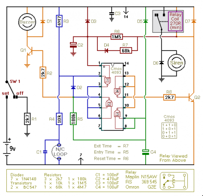
This is an improved version of the basic Garage/Shed Alarm. The Entry and Exit delays have been extended to approximately 30 seconds, and a timed siren cut-off along with an automatic reset feature has been incorporated. Additionally, the LED...
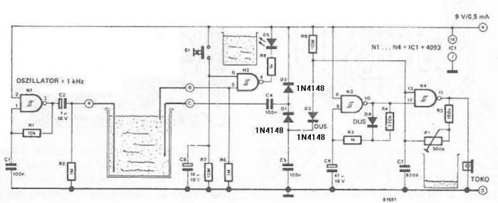
The circuit diagram is straightforward and operates as follows: the N1 Schmitt trigger functions as an oscillator, producing a frequency of approximately 1 kHz. When there is sufficient water in the tank, alternating voltage flows from electrode A to...
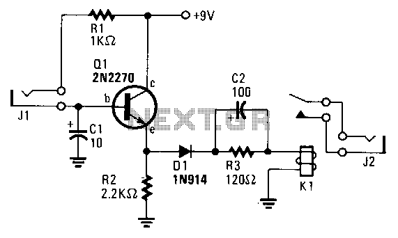
The transistor Q1 remains off until the magnetic switch connected to J1 closes. When this occurs, 9V is supplied through R1 to the base of Q1. As a result, Q1 turns on, which charges capacitor C2 through relay K1,...
When the AC mains supply fails, this circuit triggers an alarm to alert the user. Additionally, it offers a backup light to assist in locating a flashlight or other emergency lighting. This circuit is designed to provide immediate notification and...
This FM radio-controlled anti-theft alarm can be used with any vehicle having a 6- to 12-volt DC supply system. The mini VHF, FM transmitter is fitted in the vehicle at night when it is parked in the car porch...
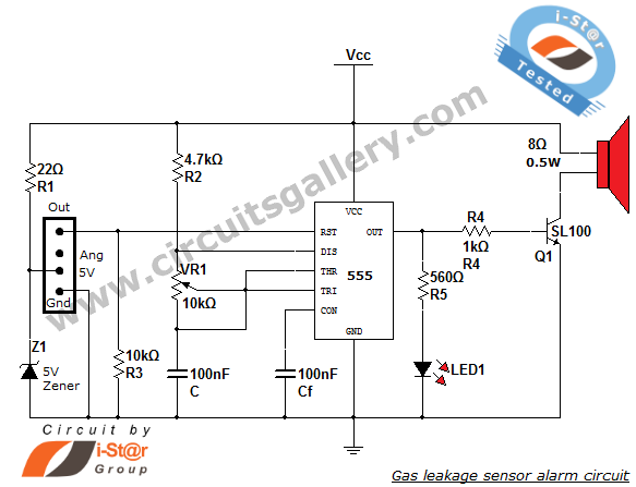
This article discusses a home security alarm circuit designed to detect LPG gas leakage. The circuit utilizes a gas sensor module, SEN 1327, which incorporates a QM 6 gas sensor. The output signal from this gas sensor module is...
Warning: include(partials/cookie-banner.php): Failed to open stream: Permission denied in /var/www/html/nextgr/view-circuit.php on line 713
Warning: include(): Failed opening 'partials/cookie-banner.php' for inclusion (include_path='.:/usr/share/php') in /var/www/html/nextgr/view-circuit.php on line 713