
Electronic Motor Starter
This motor starter circuit is designed to enhance the operational reliability of single-phase motors by incorporating several protective features. The transformer is crucial for reducing the mains voltage to a safer level, which is essential for the subsequent circuitry. The rectification process performed by diodes D1 and D2 ensures that the power supply is suitable for the protection circuit, converting AC to DC for stable operation.
The protection circuit is the heart of this design. Transistor T1 monitors the voltage level, and its adjustable threshold allows for customization based on the specific motor's requirements. This flexibility is vital for ensuring that the motor operates within safe voltage limits, preventing damage due to over-voltage conditions. Similarly, T2 acts as a safeguard against under-voltage scenarios, ensuring the motor is not subjected to insufficient voltage, which could lead to inefficient operation or damage.
Zener diodes ZD1 and ZD2 play a critical role in biasing the transistors, ensuring they operate correctly within their intended regions. The SCR-like configuration formed by T3 and T4 allows for efficient control of the motor's power state, enabling smooth transitions between on and off states.
The inclusion of switches S1 and S2 provides a user-friendly interface for manual control of the motor. The temporary disconnection of capacitor C2 during voltage adjustments is a practical design consideration, allowing for accurate settings without interference from transient voltage spikes.
The use of the regulator IC 7809 ensures that the soft switch and relay receive a stable voltage supply, which is essential for reliable operation. Capacitor C4 serves to filter any residual noise, further stabilizing the power supply.
The miniature circuit breaker is an important safety feature, providing automatic disconnection in the event of an over-current situation, thus protecting both the motor and the circuit from potential damage.
Finally, the status indicators (LED1 and LED2) allow for immediate visual feedback regarding the operational state of the motor and the power supply, enhancing user awareness and operational safety. Overall, this motor starter circuit is a well-designed solution for managing the performance and safety of single-phase motors in various applications.This motor starter protects single-phase motors against voltage fluctuations and overloading. Its salient feature is a soft on/off electronic switch for easy operation. The transformer steps down the AC voltage from 230V to 15V. Diodes D1 and D2 rectify the AC voltage to DC. The unregulated power supply is given to the protection circuit. In the p rotection circuit, transistor T1 is used to protect the motor from over-voltage. The over-voltage setting is done using preset VR1 such that T1 conducts when voltages goes beyond upper limit (say, 260V). When T1 conducts, it switches off T2. Transistor T2 works as the under-voltage protector. The under-voltage setting is done with the help of preset VR2 such that T2 stops conducting when voltage is below lower limit (say, 180V).
Zener diodes ZD1 and ZD2 provide base bias to transistors T1 and T2, respectively. Transistors T3 and T4 are connected back to back to form an SCR configuration, which behaves as an on`/off` control. Switch S1 is used to turn on the pump, while switch S2 is used to turn off the pump. While making over-/under-voltage setting, disconnect C2 temporarily. Capacitor C2 prevents relay chattering due to rapid voltage fluctuations. Regulator IC 7809 gives the 9V regulated supply to soft switch as well as the relay after filtering by capacitor C4.
A suitable miniature circuit breaker is used for automatic over-current protection. Green LED (LED1) indicates that the motor is on` and red LED (LED2) indicates that the power is on`. The motor is connected to the normally-open contact of the relay. When the relay energizes, the motor turns on. 🔗 External reference
Related Circuits

When the doorbell switch is pressed, two monostable stages are sequentially activated, applying bias to a pair of voltage-controlled resistor stages. These stages modulate the outputs from a pair of tone generators. The resulting signals are then fed to...

The semiconductor thermistor is an embedded thermal protection element that is sensitive to temperature, with a temperature error of 5 degrees. It offers reliability, a small size (diameter 3.5 mm), and ease of installation, making it suitable for embedding...
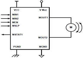
The schematic presented illustrates a 5A H-Bridge Module designed for the operation of a single Bipolar DC motor. The H-Bridge Module includes a header set (J2) and a connector terminal set (J1). Below is the pinout description for the...
S1 and S2 are normally open, push-to-close, momentary switches. The diodes may be red or green and serve solely as indicators of direction. The TIP31 transistors may need to be adjusted based on the motor specifications. It is important...
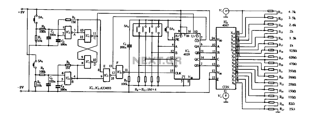
Figure 4-14 illustrates a digital integrated circuit featuring 16 preset potentiometers for Siniperca electronic circuits. The circuit comprises three main components: an input controller, a presettable counter, an analog electronic switch, and a resistor network. It includes a push-button...
DC Motor Control Using a Single Switch. This simple circuit allows for the operation of a DC motor in both clockwise and counterclockwise directions, as well as stopping it using a single switch. The circuit utilizes non-latching push button...
Warning: include(partials/cookie-banner.php): Failed to open stream: Permission denied in /var/www/html/nextgr/view-circuit.php on line 713
Warning: include(): Failed opening 'partials/cookie-banner.php' for inclusion (include_path='.:/usr/share/php') in /var/www/html/nextgr/view-circuit.php on line 713