
Your Duino Starter
The Arduino IDE serves as an essential tool for developing software sketches that control various hardware components. The software environment simplifies the coding process, allowing users to write, edit, and upload their programs seamlessly. The Robo1 board features several indicators: the PWR LED signals power status, while the two green LEDs provide feedback during data uploads. The red LED connected to pin 13 serves as a visual indicator of program execution.
To begin utilizing the board, it is crucial to establish proper connections on the breadboard. The breadboard's design allows for easy insertion and removal of components, facilitating experimentation and learning. The horizontal rows are electrically interconnected, while vertical columns provide power distribution, with the red rail typically serving as the +5V supply and the blue rail as the ground connection.
When connecting the YourDuino board to the breadboard, the TS+ and TS- pins are utilized to supply power. A 220-ohm resistor and a red LED can be connected to the breadboard to create a simple circuit that demonstrates the functionality of the Arduino. The resistor limits the current flowing through the LED, preventing damage and ensuring proper operation.
Once the circuit is established, programming the Arduino to control the LED involves writing a sketch that includes setup and loop functions. The setup function initializes pin modes, while the loop function contains the logic for blinking the LED at specified intervals. The delay function governs the timing of the LED's on and off states, allowing users to experiment with different durations to observe the effects of persistence of vision.
Overall, the integration of the YourDuino board with a breadboard and various components enables users to explore the fundamentals of electronics and programming. By following the provided guidelines and examples, users can develop their skills and create increasingly complex projects, fostering a deeper understanding of automation and control systems.This manual will show you how to use each of the components in the kit, and give you software Sketch examples for each one. Then you can combine some components to make examples of Automatic Systems such as a lighting controller.
The Arduino "IDE" software looks virtually the same on Windows, MAC or Linux, but the Installation procedures are diffe rent. Below, you can pick which one you need. (WikiPedia) is the software you use on your computer to write software Sketches and then upload and run them on the YourDuino hardware. The IDE is like a word processor for writing software. On the right, let`s look at some of the features of the Robo1 board as used in these Starter Sets. At the lower left is the PWR LED which should light up whenever the board is plugged into a USB connection, or has power from an external power supply.
At the upper left there are two green LEDs which will blink when a software sketch is being downloaded to the board, or other data is being transferred over USB. At the top is a red LED which is internally connected to pin 13 through a current-limiting resistor. It should blink after you load the example BLINK software sketch. The colored 3-pin connectors make it easy to connect many input and output devices. The Vcc(+5V) pins at upper right and the (Ground) pins at the lower right are good for connections to breadboard etc.
You should have followed the IDE Installation for your PC/MAC Operating System and now you`ve got your YourDuino plugged in and running. The POWER "ON" LED is on, right And the "13" LED is blinking (This may be a little different for the various YourDuino versions and the `13` LED may or may not blink now).
Let`s take a little while to get used to writing Arduino Software, then we`ll come back and start connecting your Starter kit parts and making more interesting things. We will give you software examples for each of the devices in the Starter Set. You`ll use this IDE (Integrated Development Environment) to make Software VISIBLE! With it you will develop your own software to make Arduino into what you want it to be. BOARD: In the Arduino IDE top menu click
Notice that a lot of the text is GRAY. All of that is just "Comments" for you to read to help understand the Sketch. When you write software, you should also use "Comments" to explain to others what you are doing. (Arduino itself totally ignores these comments). Now, let`s go through Editing software, Verifying it, and Uploading it to see Arduino DO it. We will use the YourDuino version of Blink: YourDuinoStarter_Blink. Click on the link to see it`s page. Now, highlight all the code (in the gray area), do
Change the Capital "M" to "m". Note the color changes to black. Hmmm. Click the VERIFY What LOOP does: Loop contains all the active parts of your Sketch that continue to run after SETUP is finished. It will run over and over again, forever, or until you stop it or power down. A LOT! More details later, but Verify is a program in your main computer that goes through every Instruction in your Sketch (Ignoring "Comments") and checks it against the list of valid Instructions, and checks that the structure and sequence of the statements in the Sketch are correct.
Fussy, Fussy! If they`re OK, then it "compiles" or "translates" the sketch into the machine code that Arduino actually runs on. It saves that `ready-to-run` code for you to Upload to Arduino and run. Other systems would call this process "Make" or "Compile". First, Upload runs Verify to check and compile your program. Then it communicates to your Arduino over the USB connection, resets the Arduino chip, and talks to software already on Arduino (called the BOOTLOADER(W) ) to load your new program into the Arduino`s memory.
Then it restarts Arduino and your program runs it`s SETUP section and then repeats the LOOP section. So, the first line in LOOP sets PIN 13 to HIGH. This means Pin 13 is connected to +5 Volts, and current flows through the resistor and LED that are already connected to pin 13. The LED lights up. The delay instruction just waits for a period of time. The VALUE used with delay is in Milliseconds (1/1000 second). So delay(1000); waits for 1000/1000 seconds (1 second). We`ll change that soon. Notice that every instruction is followed by the character " ; " which is like a period that tells the end of a sentence.
Run-on sentences will make you stay after school to fix your error messages! Suggestion: Save your own version of BLINK so you can always go back to the original one. Go to File and Save As and call it something like MyBlink. This will go in your SKETCHBOOK where you`ll save your own programs. So, let`s change the ON time to be short. Maybe 50 Milliseconds. That`s 1/20 of a second. Then try 10 milliseconds. The LED is only on 1/100 of the time. Can you still see it blink How about 1 millisecond which will first Verify and Compile your program and then send it to Arduino. Notice that each time you do this the LEDS that are marked "Tx" (Transmit) and "Rx" (receive) flash as your main computer communicates with your Arduino.
Try making both ON and OFF times shorter and shorter. If you make the ON and OFF times short enough your eye will no longer see blinking, because of "Persistence of Vision"(W) which happens when there are more than about 25 blinks per second. So, hmmm. if you make the LED be ON for 1/50 of a second and OFF for 1/50 of a second that should do it. So try 1000/50= 20 Milliseconds. Put 20 for both the ON and OFF times. What do you see How about 10 Milliseconds each Depending on your personal eye`s physiology, at some speed you will not see any more blinks.
Young people can usually see faster blinks. Arduino is great but sometimes connecting interesting things to it can be a pain. We tried to make it easier for you. We will use a BREADBOARD (W) for most connections. The idea here is that wires and electronics parts like LEDs and RESISTORs have wire leads that can be plugged into the BREADBOARD and then easily be removed or changed. The holes in the BREADBOARD go down into little sockets with metal contacts. The Horizontal Rows have 5 holes (abcde) and (fghij) with sockets that are connected together. Any wires or parts that are plugged into one of these rows are connected together. The Vertical Columns (+Red and -Blue) have the same connection running all the way down. We will use these to connect 5V on our YourDuino board to the +Red and to connect GND on our YourDuino board to -Blue.
Then any time we need to connect to GND, we just plug a wire or part into the -Blue column, and any time we need to connect to 5V, we just plug a wire or part into the +Red column. Now let`s look again at the YourDuinoRobo1 board and where we will make connections there. Later we will look at the board in a lot more detail, but for now let`s just hook up a few things and make them work.
The first thing we want to do is connect GND on the board to a -Blue column on the breadboard and 5V on the board to a +Red column. Notice the pin connectors on the far right of the YourDuinoRobo1, labelled TS- (which is Ground) and TS+ (which is +5V).
They are convenient to connect +5V and Ground to the breadboard. We will mainly use the upper +Red row and the bottom -Blue row. Often we think of these parallel lines as "Rails" like railroad rails. The top red rail is the "+5 Volt Rail" and the bottom blue rail is the "Ground Rail". "Voltage Rails" (W) is a common terminology in electronics. You can easily strip off one or more wires, or strip off a section to use as a cable. The ends of these wires are female connectors that can plug onto the connectors on the Robo1 or a "Sensor Shield". But what about the breadboard It needs a wire with a male end to plug into it. The pin strips (Right) are the answer. Your kit has 2 of these with 40 pins each. You can cut or snap off the number of pins you need. For now, snap/cut off about 6 single pins. It`s easier to snap off just 1 pin if you grab it with a small pair of pliers of some kind. Or you can "cut" in between the pins with strong scissors or wire cutters. Strip off 1 Blue wire and 1 Red wire from your flat cable. Run the Red wire from a +5 (TS+) pin on the YourDuino to the +Red Rail on the breadboard. Run the Blue wire from a GND (TS-) pin on the YourDuino to the -Blue Rail on the breadboard. Now it`s easy to connect things to the 5V (+Red) Rail or the GND (-Blue) Rail. We show +5 and Gnd connected to the TS pins on the far right side of the Yourduino board. See the close-up photo here, and plug a 220 Ohm (Red-Red-Brown) resistor [TBD: Color Code] and a red LED (Long pin to the left) into the Breadboard as shown.
(Use male-male pins where you need a male end to plug into the breadboard or YourDuino). Now add a wire (Black is shown) from the same vertical strip as the LED to the GND Rail. Connect another wire (Green is shown) to the same vertical strip as the left end of the resistor, and use a pin to plug it into the YourDuino socket labelled 13. OK we need to stop for a minute and make sure we understand how the breadboard, the components and wires make up Circuits we want.
🔗 External reference
Related Circuits
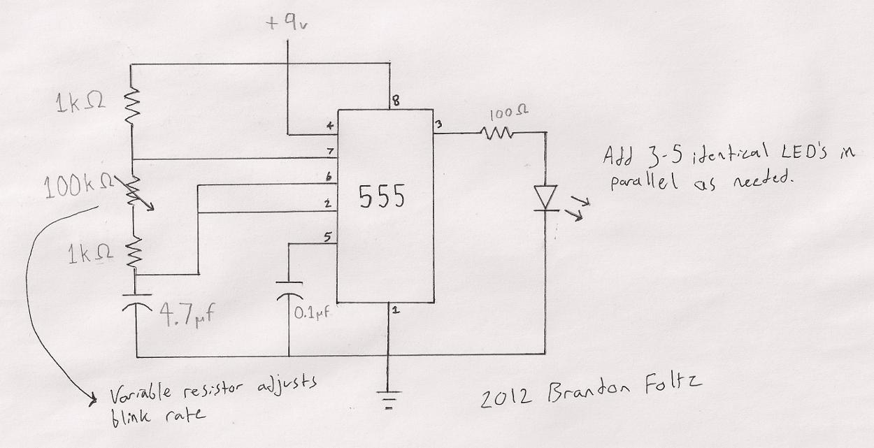
The circuit utilized is a commonly known design. A search for "555 timer LED blinker" will yield numerous schematics that are suitable for this application. The specific schematic presented includes a variable resistor (100K) that allows for user-adjustable blink...
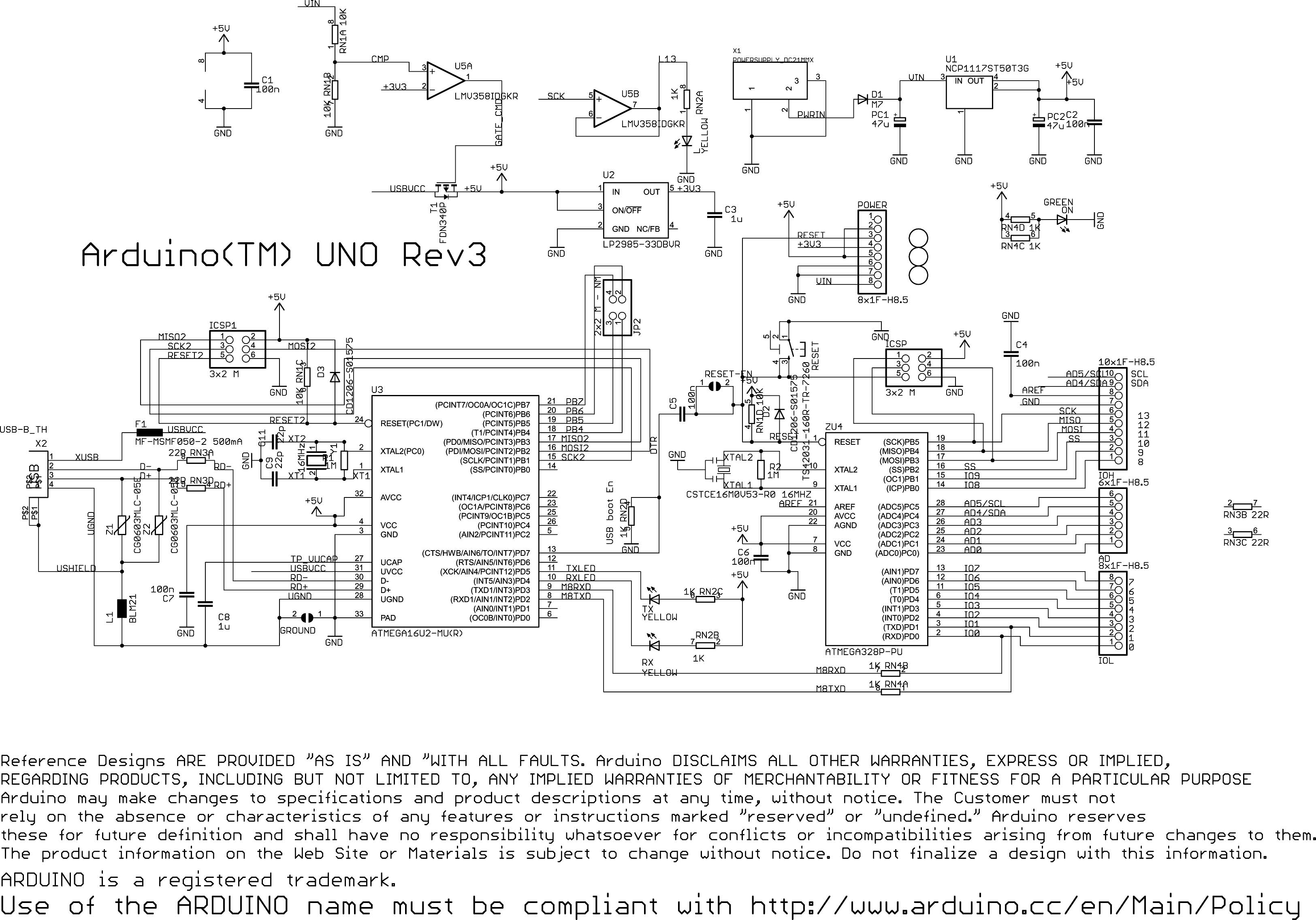
A challenge encountered when beginning to work with Arduino was determining how to create circuit diagrams for projects. There are numerous software options available for drawing schematic diagrams, some of which are free while others require payment, each presenting...

The Atmega8 microcontroller from Atmel features numerous digital and analog input/output lines, making it an ideal choice for developing various measurement equipment. It is essential to have the GCC AVR programming environment installed, as outlined in the article "Programming...
The notes for the fourth and final class are available on the Spooky Arduino class page. At the conclusion of the class, Mark from Machine Project awarded each student a merit badge. A project utilizing techniques from this week's...
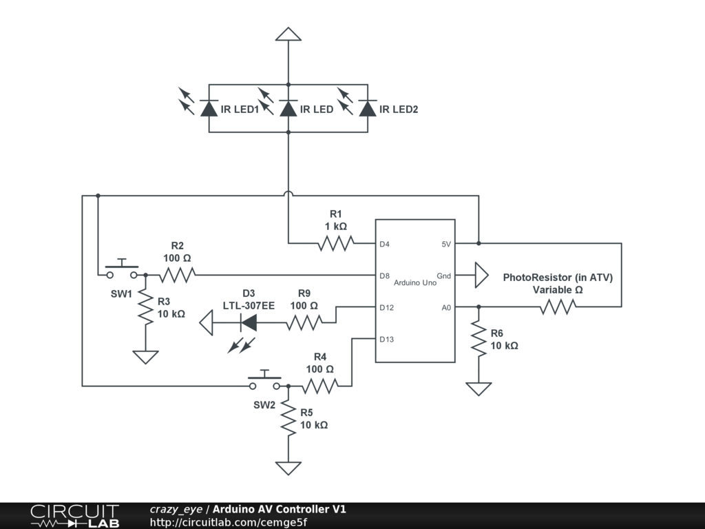
Arduino Event-Driven Universal AV Remote May 1st, 2013. Turn everything on with Airplay. The project involves the development of an Arduino-based universal remote control designed to manage various audio-visual (AV) components through an event-driven architecture. This remote utilizes Airplay...
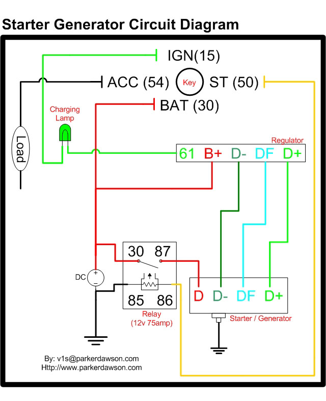
Circuit diagrams for both a Bosch and a Delco-Remy Starter-Generator are available, noting that the circuits differ. Due to a computer crash, the original diagrams and the associated email address were lost. However, in May 2004, both the email...