
Simple 6V charger battery circuit Schematic Diagram

The charger circuit employs the LM317L voltage regulator, which is an adjustable three-terminal linear voltage regulator. It is capable of providing a stable output voltage that can be adjusted to meet the specific voltage requirements of various battery types within the 9V to 30V range. The 2N222 transistor is used in this design to enhance the current handling capability, allowing the circuit to manage higher charging currents necessary for effective battery charging.
The input section of the circuit receives a direct current (DC) voltage supply, which is connected to the LM317L. The output of the LM317L is connected to the battery being charged. The 1000µF capacitor plays a crucial role in smoothing out the output voltage, reducing ripple and providing a more stable charging voltage to the battery. This capacitor helps to ensure that the battery receives a consistent voltage, which is essential for efficient charging and longevity.
The simplicity of this circuit allows for easy assembly using basic electronic components, making it accessible for hobbyists and those new to electronics. It can be constructed on a breadboard or a perfboard without the need for a PCB, facilitating a hands-on approach to learning about battery charging circuits.
Overall, this charger circuit is an effective solution for charging 9V to 30V batteries, combining reliability and ease of construction while ensuring optimal performance through the use of the LM317L and 2N222 transistor.This is very simple charger 9V - 30V battery charger with main operation by IC LM317L and 2N222 transistor. Direct input DC voltage, the recomended capacitor is 1000uf. It can be filtering Output voltage and make long-lasting battery. And easy to make this circuit, without using the PCB would be able to. You are reading the Circuits of Simple 6V charger battery circuit And this circuit permalink url it is 🔗 External reference
Related Circuits
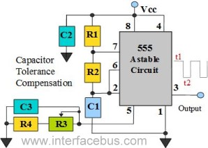
The 555 Timer is configured as an astable multivibrator. Additional components have been incorporated to enhance circuit operation. Upon powering the circuit, the 555 Timer will generate a square wave, determined by the values of Capacitor C1 and Resistors...
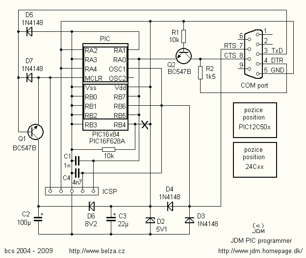
In the article you will find a description of the universal PIC programmer, which suggested the involvement of Jens Madsen Dyekjar. Program allows districts PIC12C5XX, 12C67X, 16C55X, 16C61, 16C62X, 16C71, 16C71X, 16C8X, 16F8X, serial EEPROM 24Cxx. It allows to...
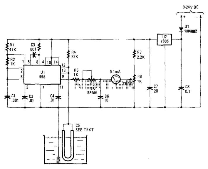
Using a capacitor sensor to detect water levels is a straightforward sensing method. This circuit employs C5, which consists of 10 to 20 inches of #22 enameled wire as one of the electrodes. The oscillator, an NE556 timer, experiences...
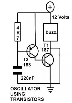
This schematic diagram represents a basic oscillator circuit utilizing two transistors. When the transistors and several passive components are connected as illustrated, the circuit begins to oscillate. The oscillation frequency can be modified by altering the values of either...
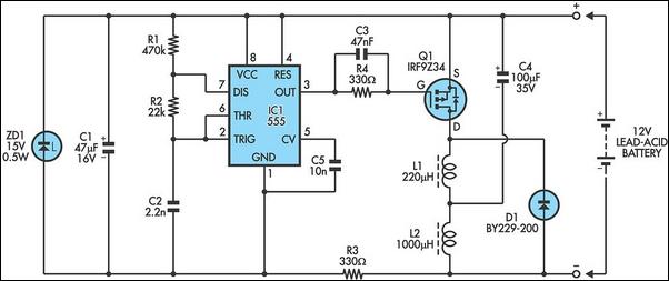
The following circuit illustrates a 6/12/24V Lead Acid Battery Charger Circuit Diagram. Features: It is essentially a high-voltage pulse generator. The circuit diagram for a 6/12/24V Lead Acid Battery Charger is designed to efficiently charge lead-acid batteries of varying voltages....
The schematic diagram below illustrates a typical 1.5V flasher circuit using the LM3909. The LM3909 is a monolithic oscillator designed specifically for flashing Light Emitting Diodes (LEDs). The LM3909 flasher circuit operates at a low voltage of 1.5V, making it...