
vna usb

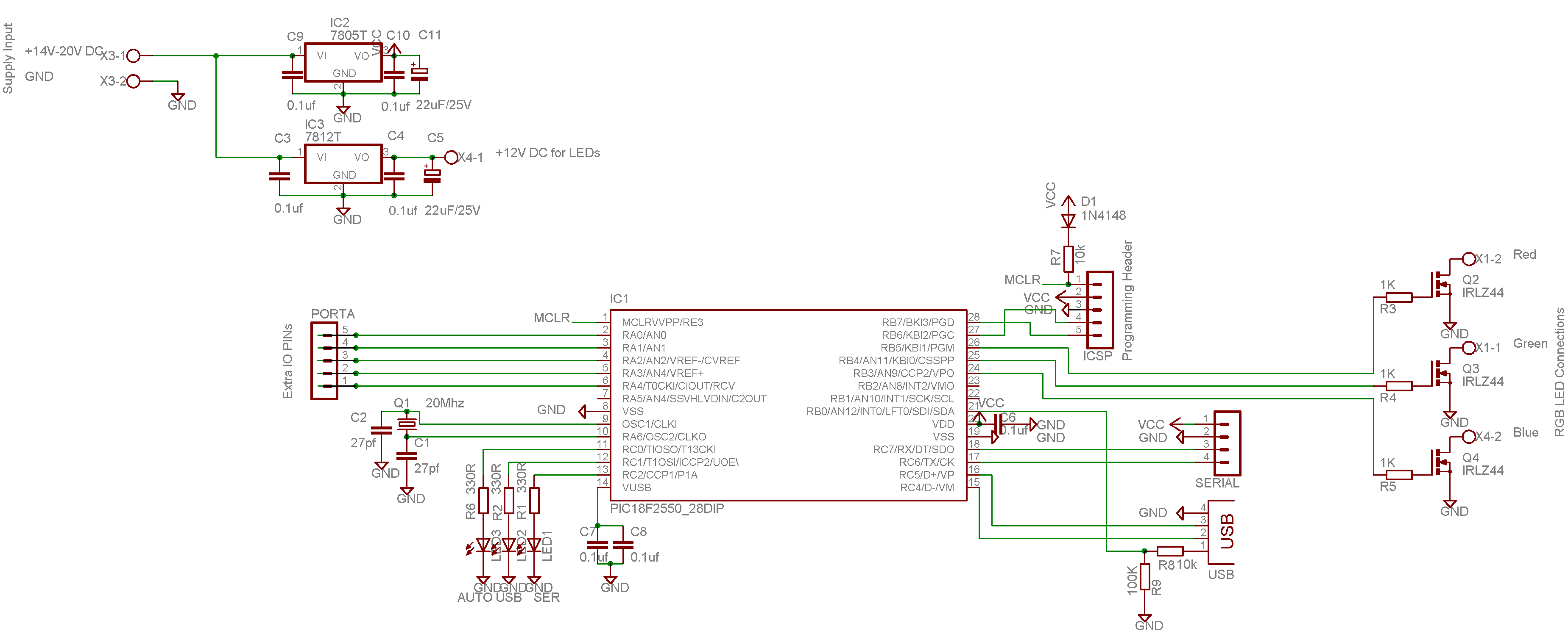
With successful communication established over the USB bus, attention turned to powering the VNA from this source. A USB port can supply 5 V at approximately 500 mA, and a quick measurement indicated that the VNA required only about 200 mA from its 5 V supply. Additionally, the VNA necessitated a nominal +12 V supply for a 7661 voltage inverter chip, which generates a low-powered -5 V supply on the VNA PCB. The +12 V supply was found to be non-critical, with a range of 7-8 volts being sufficient. The challenge involved generating 9-10 volts from the 5 V USB supply. The solution was to employ an isolated DC-DC converter found on older 10BaseT Ethernet cards, specifically the ones equipped with BNC connectors. These converters are typically housed in a 24-pin Dual In-Line Package (DIL) and are commonly manufactured by YCL, bearing the designation DC-101. While Ethernet cards of this type are no longer used for computers, they contain several useful components and can often be acquired at little or no cost. Other manufacturers also produce similar DC-DC converter parts, with standard packaging. The circuit was assembled and functioned effectively. A circuit diagram of the configuration used is available, and the VNA was successfully demonstrated measuring the characteristics of a 6 MHz crystal, without the need for an external power unit. The small tin box in front of the setup contained calibration pieces and some SMA to BNC leads.
The N2PK VNA setup exemplifies a practical application of USB interfacing and power management in electronic measurement devices. The transition from parallel to USB communication not only modernizes the functionality of the VNA but also enhances its portability and ease of use in various measurement scenarios. The use of a DC-DC converter to derive the necessary voltage levels from the USB power supply showcases an effective solution to power requirements, ensuring the VNA operates reliably in a compact, laptop-based environment. This configuration serves as a valuable reference for similar applications in antenna measurement and other RF testing scenarios, highlighting the importance of adapting legacy devices to contemporary computing environments.A N2PK VNA that it would be useful for antenna measurements and wanted to run it with a laptop PC. As most newer laptops do not have a parallel port on them I decided to explore running it off the USB port. USB has its attractions when it works properly and the idea of making the VNA plug and play appealed to me.
My initial thoughts were to try using a standard USB to parallel port cable. The problem I found with one of these devices was that WinXP insisted on identifying it as a printer and set it up as a USB printer. No doubt there is a way round this if you know more about the operation of the USB port than I do. Having found that this approach was not going to work easily I bought one of the Elrasoft Cypress EZUSB modules described on Dave Robert`s, G8KBB, website.
I followed the instructions to program the chip with the correct PID and VID for the VNA application having downloaded the EZUSB control panel from Cypress`s website. All that remained to do was to let the PC detect the USB board and wait for it to ask for the drivers etc for the VNA which I had already downloaded from Dave`s website.
Once the installer program was pointed at the folders with the *. inf files all went smoothly. Having made the VNA communicate over the USB bus my thoughts turned to powering it from the bus. A USB port can provide 5 V at around 500 mA. A quick check with a multi-meter showed that the VNA only took about 200mA from its 5 V supply. The VNA also requires a nominal +12 V supply which is used to power a 7661 voltage inverter chip. This is used to generate a low powered -5 V supply on the VNA PCB. The 12 V is clearly not very critical and anywhere above about 7-8 volts seemed adequate. The problem was to find a way of producing 9-10 volts from the 5 V USB supply. The solution was to use one of the isolated DC-DC converters that are on old 10BaseT Ethernet cards, (the ones with BNC connectors). These are packaged in a 24 pin DIL package and are commonly made by YCL and carry the marking DC-101.
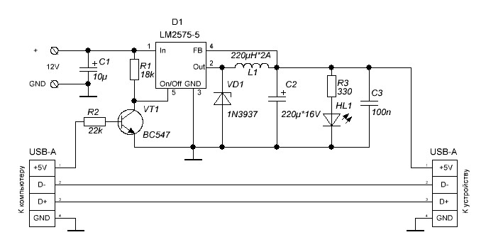
The data sheet is here. Ethernet cards of this vintage are obsolete for computer use but have a number of useful parts on them and usually can be obtained for little or no cost. There are other makers of the DC-DC converter part but the packaging seems to be fairly standard. The circuit was lashed together and all worked well. Figure 1 is a circuit diagram of the arrangement used. Figure 3 shows the VNA in action on my laptop measuring a 6 MHz crystal characteristics. Look no power unit! The small tin box in front contains the calibration pieces and some SMA to BNC leads. 🔗 External reference
Related Circuits
This color changer mixes light from high-power LEDs to create over 16 million colors. A smooth auto-fader cycles the colors, or it can be connected to a USB port for computer control. The device utilizes a well-known color model...
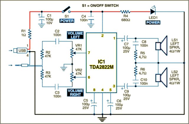
The circuit is designed as a dual audio power amplifier for use in battery-operated sound players. The TDA2822M specifications include low quiescent current, minimal crossover distortion, a supply voltage as low as 1.8 volts, and a minimum output power...
Numerous effective In-System Programming (ISP) designs are available for 8-bit AVR microcontrollers. However, many of these designs necessitate a pre-programmed microcontroller, presenting the "Chicken or Egg" dilemma: programming microcontrollers requires having one that is already programmed. While solutions utilizing...
This circuit switches a printer's USB connection between a PC and a laptop. The goal was to create a method for allowing the laptop to use the printer occasionally while maintaining the printer's connection to the PC at all...
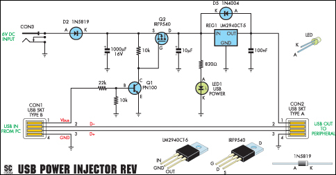
A portable USB hard drive is an effective means to back up data; however, issues may arise if the USB ports do not provide sufficient power to operate the drive. A modified version of the Silicon Chip USB Power...
Additional power supply for USB devices. Refer to the page for an explanation of the related circuit diagram. The additional power supply for USB devices is designed to enhance the power availability for devices that may require more current than...