Voice-activated toy car circuit
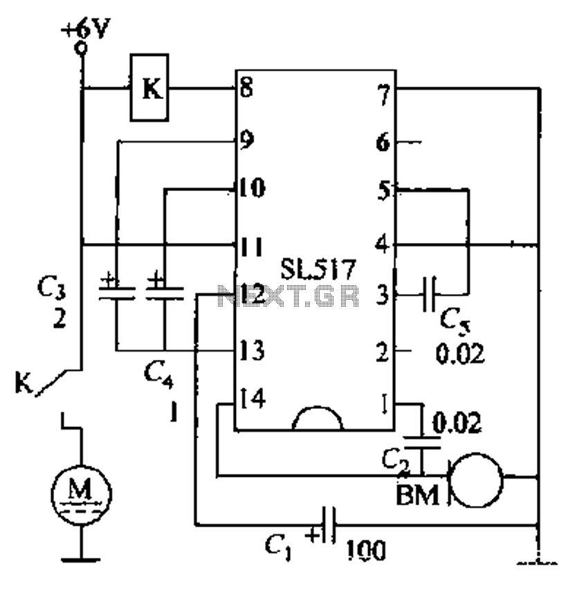
Electric cars utilize a voice circuit principle, where sound signals are captured by a microphone (BM) and processed. The signal is then coupled through a capacitor to an integrated circuit (IC), which includes an internal amplifier that boosts the weak signal. The amplified output is transmitted through a capacitor (C4) to a flip-flop circuit. The Q output of the bistable circuit is connected to a buffer that drives a control transistor (VT). When the bistable circuit output is low, the transistor is turned off, causing the external relay (K) to release. When the sound sensor detects sound, the bistable circuit output goes high, saturating the transistor and activating the relay (K), which powers the motor. Upon receiving another external sound signal, the Q output returns low, turning off the transistor and releasing the relay, stopping the motor. The microphone continuously triggers the bistable circuit, causing the relay to act repeatedly.
Electric vehicles often implement sophisticated sound detection systems to enhance user interaction and safety. The described circuit effectively demonstrates how sound signals can be utilized to control various functions within the vehicle.
The microphone (BM) serves as the initial interface, converting acoustic signals into electrical signals. The integration of a capacitor allows for AC coupling, which filters out DC components and passes only the varying sound signals to the integrated circuit (IC). The internal amplifier within the IC is crucial for amplifying weak signals that may otherwise be undetectable.
Following amplification, the signal is directed through capacitor C4 to a bistable flip-flop circuit. This flip-flop serves as a memory element, maintaining its state until triggered by an input signal. The Q output of this circuit is responsible for controlling the buffer that drives the transistor (VT).
The transistor operates as a switch within the circuit. When the output of the bistable circuit is low, the transistor remains off, and the relay (K) is deactivated, preventing any current from reaching the motor. Conversely, when sound is detected, the bistable circuit's output transitions high, saturating the transistor and activating the relay. This action allows current to flow to the motor, initiating its operation.
The relay provides a mechanical means of controlling higher power devices, such as motors, based on low-power signals from the control circuitry. The design ensures that the motor operates only in response to sound signals, enhancing the vehicle's functionality while minimizing the risk of unintended activation.
In summary, the circuit effectively demonstrates how sound detection can be harnessed to control motor functions in electric vehicles, utilizing a combination of microphones, amplifiers, flip-flops, and relays to create a responsive and efficient system.Electric cars represent the voice circuit principle, when to speak, against sound signal received by a drop in the body into a microphone BM and telecommunications weak number, G via a capacitor coupled to an integrated circuit O feet, by the internal amplifier IC emblem weak signal amplified, and then by the pin output, amplified signal is coupled via a capacitor C4 and C input to flip-flop together end a ? feet and legs. The Q output of bistable circuit connected buffer punch drive control transistor VT off and turned on.
If the original bistable circuit output terminal is low, the transistor is turned off, external relay K release. The sound sensor receives sound, the bistable flip the circuit is high, crystal tube by the deadline becomes saturated conduction, the relay pull-K, was charged with motor power and start working.
When the sensor receives external sound again, Q goes low again, crystal transistor is turned off, the relay K release, accused the motor to stop working. After the microphone whenever they receive a signal circuit bistable flip once, will relay the action again.
