
Voice-Modulated Pulse Fm Ir Transmitter
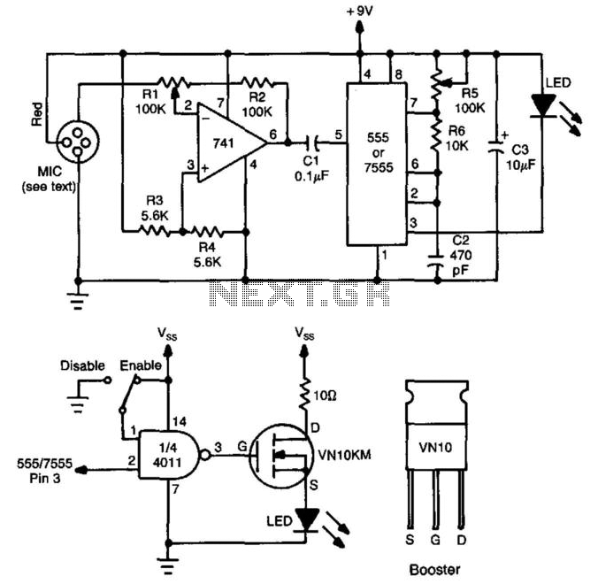
The circuit design begins with the 741 audio amplifier, which amplifies the audio signal captured from the microphone. The microphone should be of an amplified type to ensure sufficient signal strength for further processing. The output from the audio amplifier is then fed into an FM modulator, which modulates the audio signal onto a carrier frequency. This modulation process allows the audio signal to be transmitted over a longer distance using radio frequency waves.
A CMOS timer, configured as a voltage-controlled oscillator, is integrated to produce a square wave output. This output is essential for pulsing the LED, which emits infrared light. The frequency of the pulsing can be adjusted by varying the control voltage supplied to the timer, allowing for flexibility in the modulation frequency.
The pulsed output from the CMOS timer activates the LED, creating a pulsed IR beam that carries the FM-modulated audio signal. This IR beam can be detected by a compatible receiver, which demodulates the signal back into audio for playback.
Additionally, a booster circuit can be included in the design to amplify the IR signal, thereby increasing the effective range of the transmission. This can be particularly useful in applications where the distance between the transmitter and receiver is significant.
Overall, this circuit effectively combines audio amplification, frequency modulation, and infrared transmission to create a versatile communication system that can be utilized in various applications, including remote audio transmission and wireless audio systems. This circuit has a 741 audio amplifier, which is fed by a microphone (use an amplified type), an FM modulator, and a CMOS timer that acts as a VCO. The LED is pulsed with the timer output (the booster circuit can be used for increased range). This yields an FM-modulated, pulsed IR beam. 🔗 External reference
Related Circuits
The power output of most of these circuits is very low because no power amplifier stages were incorporated. The transmitter circuit described here has an extra RF power amplifier stage, after the oscillator stage, to raise the power output...
A 40kHz ultrasonic transmitter circuit consists of three oscillators (F1, F2, and F3), with F3 generating a 40kHz square wave output. The frequency is primarily determined by components C1, R1, and an adjustable resistor (RP). The excitation output from...
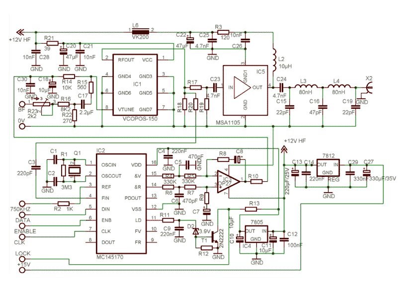
This new FM transmitter is very easy to make and doesn't need any RF tuning. First of all, we have used an integrated VCO: The POS150 from Mini-circuits. This excellent RF circuit covers all the FM Band in a...
An FM transmitter circuit that utilizes a low power configuration, employing an operational amplifier as an audio preamplifier and a single transistor to function as the RF amplifier. This FM transmitter circuit is designed for low power applications, making...
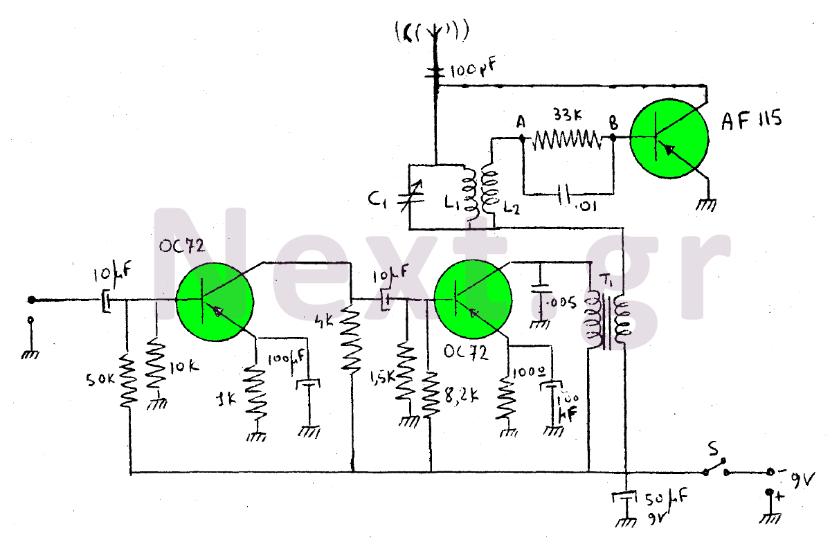
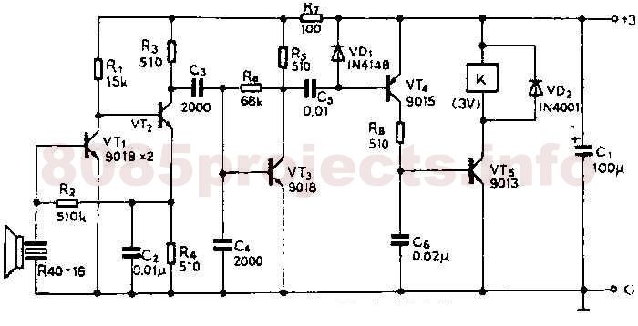
This device is a transmitter operating on medium-wave and short-wave frequencies, utilizing three transistors. The AF115 transistor serves as the oscillator within the circuit. The low-frequency amplifier, consisting of two OC72 transistors, functions as the modulator that generates the...

This transmitter operates on a 9-V battery and can function as a wireless microphone compatible with standard 88- to 108-MHz FM broadcast receivers. To adhere to FCC regulations, the antenna length should not exceed 12 inches. The inductor L1...