
Voltage Controlled Voltage Source
This circuit design serves as a voltage-controlled voltage reference, effectively utilizing an n-channel MOSFET to regulate output voltage while maintaining the operational limits of the op-amp. The integration of the MOSFET allows for higher output voltage capabilities without exceeding the op-amp's voltage supply constraints. Selection of R1 and R4 is critical; these resistors must ensure that the gate-source voltage of the MOSFET does not exceed its maximum rating, which is essential for reliable operation.
The feedback mechanism of the op-amp is modified in this configuration, with the control voltage applied to the non-inverting input while the feedback input is routed to the inverting terminal. This arrangement allows for effective voltage regulation based on the applied control voltage. The feedback loop is designed to maintain stability, and the inclusion of a capacitor at the output serves to mitigate potential oscillations that may arise from feedback fluctuations. Care must be taken to avoid placing any capacitive elements across the feedback resistors, as this could lead to instability in the circuit.
Overall, this circuit provides a robust solution for applications requiring a stable voltage reference that can operate above the typical supply limits of standard op-amps, making it suitable for a variety of electronic design projects.The disadvantage of the circuit above is that the supply of the op-amp is tied to the HV supply. Most op-amps are limited to around 30V on the supply, so the circuit wont work for higher output voltages. The circuit below avoids this this problem by inserting a n-channel mosfet, which can be fully controlled within the range of the op-amps power s
upply. The output voltage is directly proportional to the control voltage. R1 and R4 should be chosen such that Vgs(max) of Q2 is never exceeded. Likewise Q2 should have an Idss greater than VHV. The circuit below is a voltage controlled voltage reference. The output voltage is directly proportional to the control voltage. Note that the control voltage and feed back input of the op-amp is swapped. The capacitor stops oscillation, and should only be placed on the output. The circuit will tend to oscillate if a capacitor is placed across the feedback network, for example across R9. Do you need help with an electronics design Daycounter provides contract electronics design services.
Contact us to give you a quote on your electronics design project. 🔗 External reference
Related Circuits
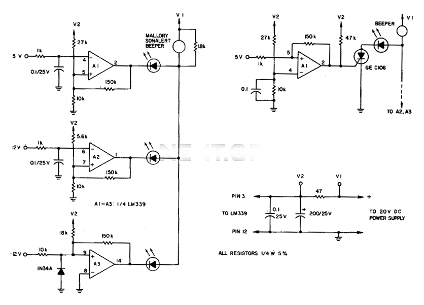
To maintain an alarm condition when an overvoltage transient disappears, an SCR should be added to the comparator circuits. For SCR operation, the voltages to the comparator inputs are inverted. The triple-voltage monitoring circuit detects transient power-supply over-voltages. If...
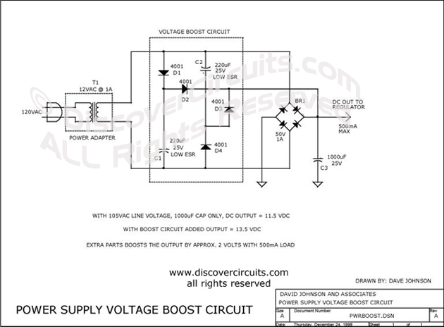
This circuit incorporates capacitors and diodes into a conventional transformer-based series regulator circuit to enhance its operational range. It ensures regulation under low line voltage conditions and can extract additional power from a standard plug-in power supply. The described circuit...
This voltage-controlled frequency divider circuit produces lower frequency pulses that depend on the control voltage, with synchronous rising edges for the input and output pulses. Typically, such frequency dividers utilize a monostable circuit connected between an inverted output and...

When the supply voltage drops below a minimum threshold, it is often advisable to disconnect the supply from the system to prevent poor performance or erratic operation. The circuit presented achieves this with minimal cost, board space, and complexity....
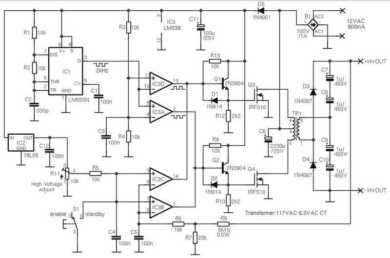
The schematic diagram is derived from the circuit for an Adjustable High Voltage Power Supply, which can output voltages ranging from 0 to 1000V. A suitable source of alternating voltage for the high voltage converter is 12V / 800mA....
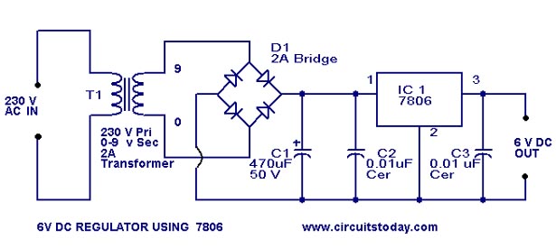
A simple 6-volt DC regulator circuit with a diagram and schematic using the 7806 IC, a positive voltage regulator. It serves as an elementary 6-volt, 1-ampere power supply circuit. The 7806 voltage regulator is a widely used integrated circuit that...
Warning: include(partials/cookie-banner.php): Failed to open stream: Permission denied in /var/www/html/nextgr/view-circuit.php on line 713
Warning: include(): Failed opening 'partials/cookie-banner.php' for inclusion (include_path='.:/usr/share/php') in /var/www/html/nextgr/view-circuit.php on line 713