
Voltage-controlled voltage source second order band-pass filter circuit
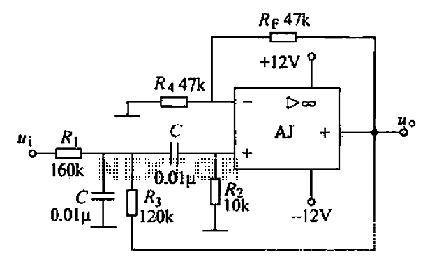
The band-pass filter is a critical component in various electronic applications, particularly in communications and signal processing. It is designed to allow frequencies within a certain range to pass while attenuating frequencies outside this range. The design typically employs a second-order configuration, which provides a steeper roll-off at the cutoff frequencies compared to first-order filters, thereby improving selectivity.
In the proposed voltage-controlled voltage source (VCVS) configuration, the filter's bandwidth can be dynamically adjusted. This is achieved by varying the control voltage applied to the filter circuit, which alters the reactive components (such as capacitors and inductors) in the filter design. This feature is particularly useful in applications where the signal environment may change, allowing the filter to adapt without needing physical modifications.
The use of the AJ dual op-amp vA747 in this circuit provides several advantages. The operational amplifier's high gain and low noise characteristics contribute to the overall performance of the filter. The dual configuration allows for the implementation of multiple stages within a compact layout, enhancing the circuit's efficiency and reducing component count.
The design of the band-pass filter involves selecting appropriate resistor and capacitor values to set the desired center frequency and bandwidth. The center frequency, defined as the frequency at which the filter's response is maximized, can be calculated using the formula:
\[ f_c = \frac{1}{2\pi\sqrt{LC}} \]
where \( L \) is the inductance and \( C \) is the capacitance in the circuit. The quality factor, \( Q \), which determines the selectivity of the filter, can also be adjusted through component values.
In practical applications, this band-pass filter can be utilized in RF communication systems, audio processing, and any system where signal integrity is paramount. By maintaining a sharp cutoff and allowing for dynamic bandwidth adjustment, the filter can effectively isolate desired signals from unwanted noise, enhancing overall system performance. Band pass filter allows only signals within a certain frequency range pass through rather than the pass band lower frequency than the upper limit of the low and high frequency signals are to be attenuated or suppressed. A typical voltage-controlled voltage source second order band-pass filter as shown in FIG. The advantage of this circuit is to change the ratio of wind RF bandwidth can be changed without affecting the center frequency. FIG integrated operational amplifier AJ dual op amp vA747.
Related Circuits
This circuit is a musical doorbell. When the button S1 is pressed, a short melody plays. If the button is pressed multiple times in quick succession or held down, a different melody is generated, and the melody plays for...
A 1.2-kHz oscillator utilizing a potentiometer and steering diodes allows for a duty cycle adjustment ranging from 1% to 99%. The frequency can be altered by varying the capacitor CI. It is important to note that the diodes may...
Artificial hatching or breeding of tropical fish requires the configuration of an oxygen pump and a circulating pump for the fish pond. Continuous operation of both pumps not only wastes energy but also risks damaging components. This example illustrates...
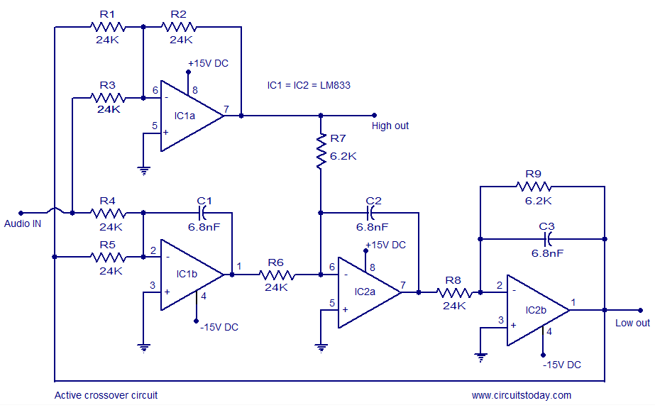
Active crossover circuit design, circuit diagram, schematic, DIY active crossover circuit, HiFi audio crossover, 2-way crossover circuit using LM833. The active crossover circuit is an essential component in high-fidelity audio systems, allowing for the separation of audio signals into different...
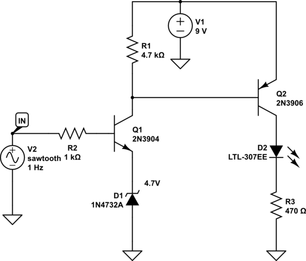
A LED is used to indicate when a DC voltage reaches 5 volts or more. The LED should be fully illuminated at 5 volts and not dim at 4.5 volts or lower. The circuit should be constructed using discrete...
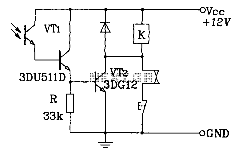
A Darlington phototransistor serves as the primary component for the photoelectric function within a self-locking control relay circuit. The circuit utilizes a Darlington phototransistor, which is known for its high current gain and sensitivity to light. This device is configured...
Warning: include(partials/cookie-banner.php): Failed to open stream: Permission denied in /var/www/html/nextgr/view-circuit.php on line 713
Warning: include(): Failed opening 'partials/cookie-banner.php' for inclusion (include_path='.:/usr/share/php') in /var/www/html/nextgr/view-circuit.php on line 713