
Photoelectric control relay circuit Darlington type phototransistor with self-locking function

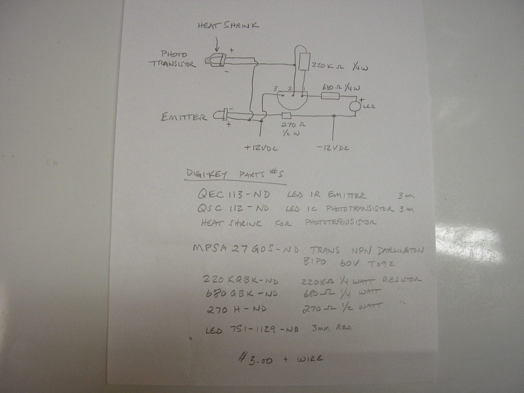
The circuit utilizes a Darlington phototransistor, which is known for its high current gain and sensitivity to light. This device is configured to detect light levels and, upon receiving sufficient illumination, activates a control relay. The self-locking feature of the circuit ensures that once the relay is engaged, it remains in the 'on' state even after the light source is removed, until a separate reset mechanism is triggered.
In detail, the Darlington pair configuration enhances the phototransistor's capability by allowing a small input current from the light to control a larger output current that activates the relay. The circuit typically includes a resistor to limit the current flowing through the phototransistor and a capacitor that may be used to filter out noise, ensuring stable operation.
The relay, when energized, can control larger loads, making this arrangement suitable for applications such as automatic lighting systems, security alarms, or other automation tasks where light detection is essential. The self-locking mechanism is often implemented using feedback from the relay to the phototransistor circuit, ensuring that the relay remains activated until an external reset signal is applied, thus providing a reliable and efficient control solution.Darlington phototransistor constituting the photoelectric function with self-locking control relay circuit:
Related Circuits
Utilizes a barium titanate transducer as a microphone, tuned with a 20 mH coil to generate peaks at control frequencies of 38.5 kHz and 41.5 kHz. A balanced discriminator detects the two ultrasonic tones. A frequency shift in the...
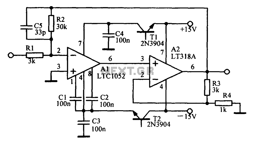
Amplifying circuit diagram to enhance the output current and voltage. An amplifying circuit is designed to increase the amplitude of an input signal, resulting in a higher output current and voltage. This type of circuit is commonly utilized in various...
Model Railroader is the world's largest magazine on model trains and model railroad layouts. It offers assistance for both beginners and advanced enthusiasts across all model railroading scales, including layout track plans, product reviews, news, and forums. Model Railroader magazine...
This circuit illustrates a color sensor circuit diagram. The design is grounded in the principles of optics and digital electronics. The color sensor circuit typically employs a light-sensitive component, such as a photodiode or phototransistor, to detect and differentiate colors...
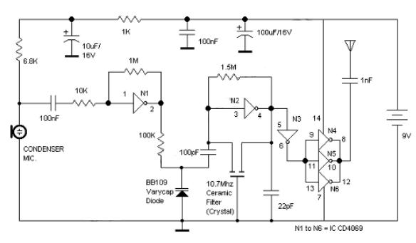
Logic Gates FM Transmitter Circuit Electronic Circuit Schematic Wiring Diagram. The FM transmitter circuit utilizing logic gates is a fundamental electronic design that operates by modulating a carrier frequency with an audio signal. This circuit typically consists of various logic...
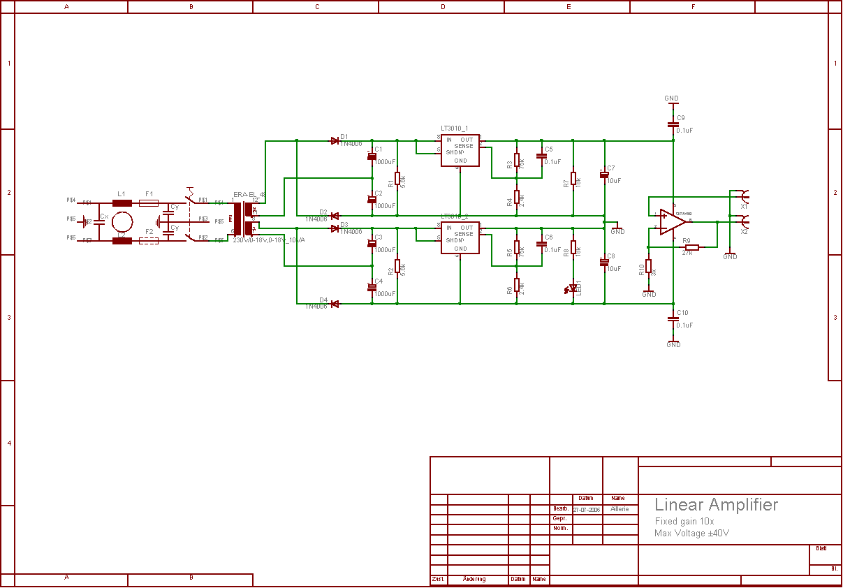
The aim of this project was to develop a linear analogue amplifier designed for laboratory use. This amplifier has to realise a voltage amplification of 10x and is intended to amplify function generator signals for tests. Power supply requirements:...