
Musical Doorbell Circuit
The musical doorbell circuit utilizes a combination of digital and analog components to create an interactive sound output based on user input. The core of the circuit is the 4015 static 4-bit shift register, which holds binary data that represents different melodies. The user interaction begins with the pressing of switch S1, which serves as the input trigger for the system. This switch closure alters the logic levels at the inputs of U3 and U1, initiating the melody playback sequence.
The clock generation is handled by U4, which provides a consistent timing pulse at approximately 5 Hz. This frequency determines how quickly the shift register advances its stored data. The duration for which the switch S1 is pressed directly influences the number of shifts that occur within the register, hence affecting the length of the melody played.
As the logic 1 is shifted through the register, it activates the base of transistor T1, which functions as a current-controlled oscillator. The oscillation frequency, and thereby the pitch of the tones produced, varies based on the specific outputs of the shift register that are active at any given moment. The feedback loop from pin 2 of the shift register back to U2 and U3 ensures that the circuit continuously cycles through the stored melodies, providing a dynamic and engaging auditory experience.
This design effectively combines digital logic with analog control to create a versatile musical doorbell that responds to user interaction in a meaningful way. The result is a circuit that not only serves its primary function as a doorbell but also adds an element of playful interaction through its musical capabilities.This featured circuit is a musical doorbell. After the button S1 is pressed, a short melody is played. When the button is pressed many times in rapid succession or pressed longer, a different melody is generated and the melody plays longer. The circuit works this way: when the button S1 is activated the inputs of U3 and one input of U1 switches to logic 0 ³.
The data input (pin 7 of IC 4015) becomes logic 1 ³. The 4015 is a static 4-bit shift register. Each clock impulse coming from U4 shifts this logic 1 ³ further in the register. The clock frequency is around 5 Hz. The number of shifted logic 1 ³ is directly dependent on the length of time the switch S1 is closed. Once at least one shift register is logic 1 ³, a current flows to the base of T1 through a corresponding resistor. The transistor T1 functions as a current controlled oscillator. The tone pitch is dependent on the logic state of the different flip-flop outputs of the shift register.
Each clock pulse shifts the logic 1 ³ in the register. One output of the register (pin 2) is coupled back to U2 and U3 so that all the logic 1 ³ in the register always run in a loop. 🔗 External reference
Related Circuits
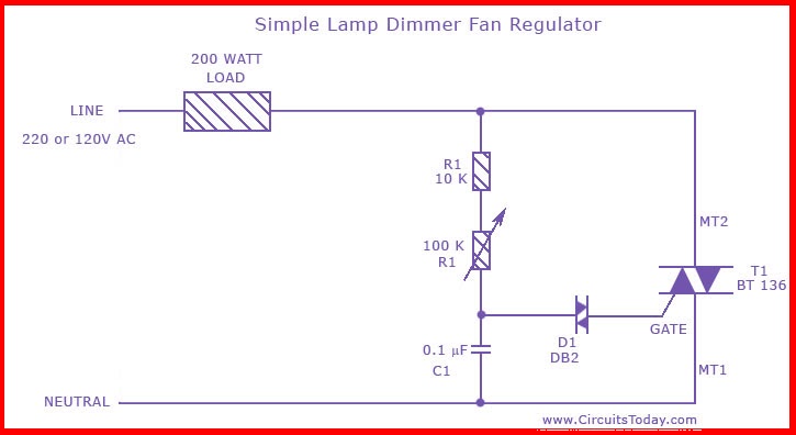
This is the circuit diagram of the simplest lamp dimmer or fan regulator. The circuit is based on the principle of power control using a Triac. The circuit operates by varying the firing angle of the Triac, which is...

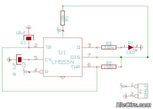
When the preset is set to its maximum, the LED flashes at a rate of approximately once every half second. This rate can be increased by raising the capacitor value from 10µF to a higher value. For instance, if...
This is a very simple 555 timer circuit that serves as a straightforward theft deterrent, which may be just as effective. The idea is to have a flashing red LED indicate that your car is protected. This device can...
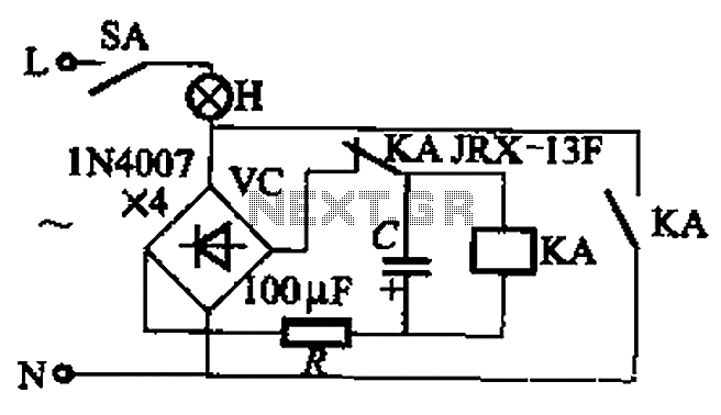
The circuit illustrated in Figure 13-3 consists of two configurations: (a) a DC power supply and (b) an AC power supply. Both configurations are utilized to control a relay. The flash frequency of the relay is determined by the...
The IC1 is a 555 timer IC connected for astable operation. The clock pulses are fed to the IC2 via the 10K resistor. The IC2 is a 10-stage counter; output 6 (pin 5) is connected to RESET (pin 15),...

A circuit is needed to drive three or more LEDs at a current of 200-350mA each, with the capability to randomly flash or strobe them at a frequency of 5-20Hz. The input power should be low-voltage DC, with a...