
Voltage Gauge

The circuit employs the RCA CA3162E A/D converter, which is integral for converting analog signals into digital format. This component is particularly notable for its 12-bit resolution, allowing for precise representation of the input signals. The BCD output from the A/D converter is interfaced with a display driver (IC1), which is responsible for driving the display elements.
The power supply for the circuit is established through IC1, which outputs a regulated +5 V necessary for the operation of the A/D converter and other associated components. The calibration of the gauge unit is critical for accurate readings; thus, R11 is adjustable to ensure that the output reflects the true value of the measured parameter. Meanwhile, R17 is set to zero, serving as a baseline for the calibration process.
The choice of common cathode displays simplifies the design, as it eliminates the need for additional limiting resistors. This is advantageous because the output drivers are designed to provide a constant current, ensuring consistent brightness and clarity of the display without the risk of damage from overcurrent conditions.
The resistors R15 and R16 play a vital role in voltage sensing. By sampling the applied voltage, which typically falls within the range of 8 to 18 V, these resistors allow the circuit to monitor and display the relevant measurements accurately. The inclusion of LED1 enhances the user interface by providing visual cues through illumination, indicating the parameters being measured, such as voltage and temperature. This design approach not only improves functionality but also enhances user experience by making the gauge readings easily interpretable. This circuit uses an RCA CA3162E (IC2) A/D converter. This converter has 12-bit output (BCD) which is sent to display decoder driver IC1. +5 V is obtained from IC1. R17 adjusts to 0 and Rll should be set to produce correct calibration of gauge unit. Displays are common cathode types. No limiting resistors are necessary because the output drivers are constant current. R15 and R16 sample the applied voltage (usually 8 to 18 V). LED1 is used to illuminate the gauge legend (Volts, Temp, etc.).
Related Circuits
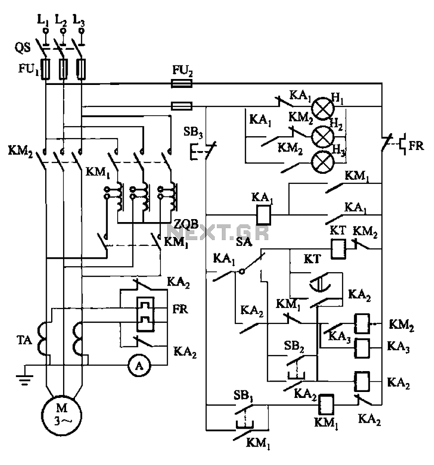
The circuit illustrated in Figure 3-56 features both manual and automatic start-up modes. It incorporates two relays, KA2 and KA3, within the control loop. The circuit design ensures that KM1 is cut off before and after activating KM2. A...
The AD652 Synchronous Voltage-to-Frequency Converter (SVFC) is a robust component designed for precision analog-to-digital conversion, featuring a typical nonlinearity of 0.002% (maximum of 0.005%) at an output frequency of 100 kHz. Its inherent monotonicity in the transfer function and...
This circuit will provide an indication whenever the input voltage differs from two defined limits, V1 and V2. The supply voltage, Vcc must be higher than the highest input voltage by at least 2 volts. One application here is...
High voltage current sensing and monitoring can be designed using the LTC6101 operational amplifier. The current sensing circuit outlined is capable of measuring electrical current. The LTC6101 is a precision current sense amplifier designed to operate in high voltage environments,...
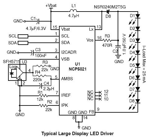
This high-voltage white LED driver electronic circuit schematic utilizes the NCP5021 integrated circuit from On Semiconductor. The NCP5021 is designed with an ambient light sensing feature and can drive up to eight LEDs in series for portable backlight applications....
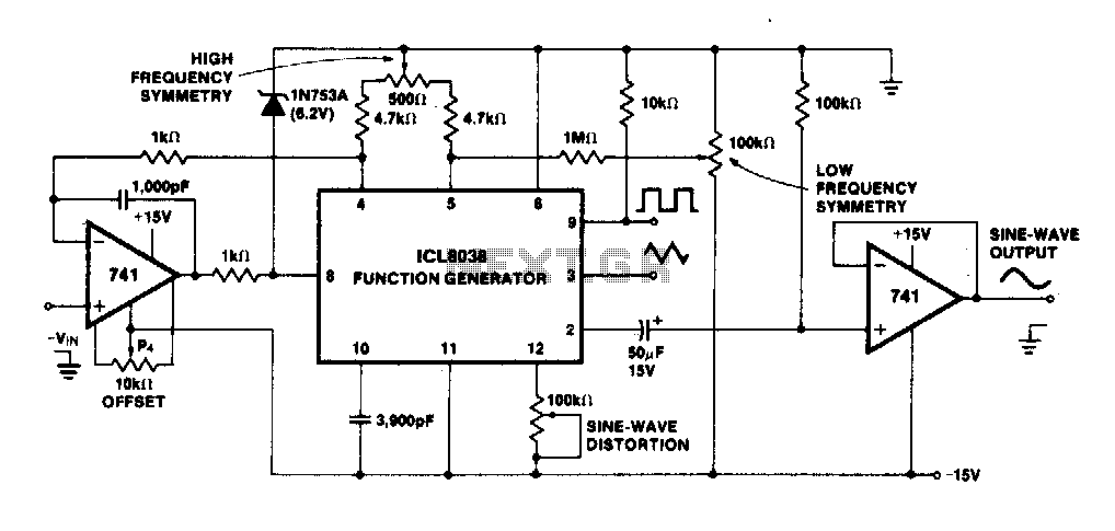
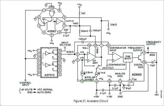
The linearity of the input sweep voltage in relation to the output frequency is significantly enhanced by utilizing an operational amplifier. The utilization of an operational amplifier (op-amp) in electronic circuits is a common practice to improve the linearity of...