
Voltage-Level Indicator

The LM78LXX series of three-terminal linear voltage regulators are widely utilized in various electronic applications due to their simplicity and effectiveness in providing stable output voltages. The device operates by maintaining a constant output voltage (Vout) as long as the input voltage (Vm) remains within specified limits, specifically 1.5 to 2 volts above Vout. This characteristic makes the LM78LXX suitable for applications where voltage regulation is critical, such as in powering LEDs or other low-power devices.
In the context of LED operation, the circuit requires a minimum differential voltage of 1.5 V between the input and output to ensure proper illumination. The LED will turn on when the input voltage exceeds the combined value of the regulated voltage (Vreg), the voltage drop across the current-limiting resistor (IR), and an additional 1.5 V. The typical forward current for the LED is approximately 6 mA, which can be managed by using a resistor or a zener diode to limit the current, thus protecting the LED from excess current that could lead to failure.
In automotive applications, the circuit's ability to indicate battery voltage levels is particularly useful. When the battery voltage exceeds 13.5 V, the circuit signals that the alternator and regulator are functioning properly, providing a visual cue through the illuminated LED. Conversely, when the engine is turned off, the battery voltage drops to around 12 V, which results in the LED turning off, indicating that the system is not charging. This functionality is crucial for monitoring the health of the vehicle’s electrical system without requiring complex calibration or setup, making it an efficient solution for automotive diagnostics.
Overall, the LM78LXX voltage regulator circuit exemplifies a practical and straightforward approach to voltage regulation and monitoring, with applications extending beyond automotive systems to various electronic devices requiring stable voltage levels. Three-terminal regulator device (LM78LXX) has Vout = Vm until the input rises 1.5 to 2 V above the output when the regulated voltage Vreg = XX is obtained. A differential of 1.5 V between input and output is necessary to light the LED. Thus, the LED lights when Vm rises above Vreg + IR + 1.5 V, where lis typically 6 mA (a zener diode could be used in place of R). For input voltages much higher than necessary to light the LED, a current-limiting resistor in series might be necessary.
A useful automotive application is shown in Fig. 14-9(b). The circuit indicates when battery voltage is above 13.5 V which indicates (in conjunction with an ammeter) whether the alternator/regulator/battery system is operating correctly. With the engine off, the battery voltage drops to 12 V and the LED extinguishes. The circuit requires no calibration.
Related Circuits
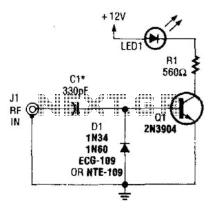
A simple RF detector circuit utilizing a visual indicator can serve as an RF output indicator. This circuit was designed for use as a transmitter ON indicator. The RF detector circuit typically consists of a few key components: a diode,...
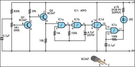
This circuit can be used to remotely monitor a loudspeaker, alarm, or audio source for presence of an audio waveform. It can also be directly connected across loudspeaker terminals used as a peak indicator. If you need to monitor...

Two TTL ICs and a handful of other components are all that is needed for a circuit that will indicate which of four buttons was pressed first, as well as lock out all other entries. A logic 0 at...
This design integrates power-on and low-battery indication features, capable of operating with any battery voltage up to 15V. It exhibits a very low current drain of 2mA or less. The circuit design incorporates a power-on indicator that activates when the...
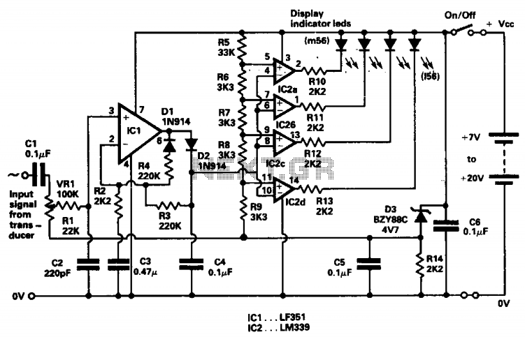
The indicator was designed to display the peak level of small AC signals from various transducers, including microphones, strain gauges, and photodiodes. The circuit responds to input signals within the audio frequency spectrum, specifically from 30 Hz to 20...
The circuit was designed to provide an indication before a 12 V lead-acid battery reaches a discharged state using an LM723 voltage regulator and a positive NPN standard voltage. The circuit utilizes the LM723 voltage regulator, which is well-suited for...