
voltage to frequency converter
The voltage-to-frequency converter circuit operates by converting an analog voltage signal into a corresponding frequency signal, which can be easily read by a frequency counter. The core of the circuit includes a resistor-capacitor (RC) network, where the resistor R2 and capacitor C1 play crucial roles in setting the time constant for the conversion process. The output frequency is generated through a comparator or Schmitt trigger configuration, which ensures that the output pulses are clean and adhere to TTL logic levels.
The choice of components is significant for maintaining accuracy and stability. Metal film resistors are preferred due to their low temperature coefficient and high precision, which contribute to the overall performance of the circuit. The multiturn trimmer resistor allows for fine-tuning of the resistance, enabling the user to calibrate the converter to achieve the desired conversion factor accurately.
The output pulse width of 5 µs ensures compatibility with standard frequency counters, allowing for reliable measurement of the frequency output. As the input voltage increases, the frequency output increases linearly, making it straightforward to interpret the voltage level based on the frequency reading. The design is particularly suitable for applications where a digital readout of voltage is required, such as in laboratory settings or for educational purposes, providing a cost-effective solution without compromising functionality.
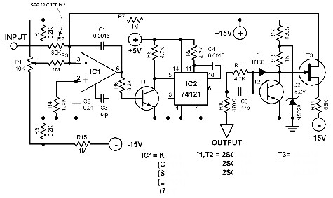
In summary, this voltage-to-frequency converter circuit is a versatile tool for converting DC voltage levels into easily measurable frequency outputs, with careful consideration given to component selection to ensure precision and reliability.This voltage to frequency converter is designed to be connected to a frequency counter to display the voltage value being measured. This converter-counter combination produces a cheap but functionally complete digital voltmeter. The circuit delivers TTL compatible pulses which are 5 µS wide. The pulse frequency is proportional to the DC voltage b eing measured. The conversion factor is 10 kHz per volt. When the input level is 0 V the frequency output is 0 Hz. The resistor R2 (together with C1) determines the conversion factor and has the value of around 90 K. To achieve best results use a metal film resistor for R2 in series with a multiturn trimmer resistor.
This multiturn resistor will enable you to set the correct resistance value. Resistors R9 and R14 must be metal film types. 🔗 External reference
Related Circuits
Another application of the frequency-to-voltage converter (FVC) is as a tone or frequency decoder. This circuit is utilized to identify the frequency band of an oscillation. The frequency-to-voltage converter (FVC) serves as an essential component in various electronic applications, particularly...
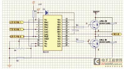
The variable frequency power supply is a crucial component of the power system, as its characteristics significantly impact the security and reliability of the overall system. The modern variable frequency power supply is characterized by low power consumption and...
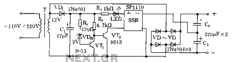
The circuit is automatically converted to a low-voltage configuration. A 220V AC supply is stepped down by transformer T. After this, the breakdown voltage of diode VDw causes transistors VT1 and VT2 to turn off, resulting in the solid-state...
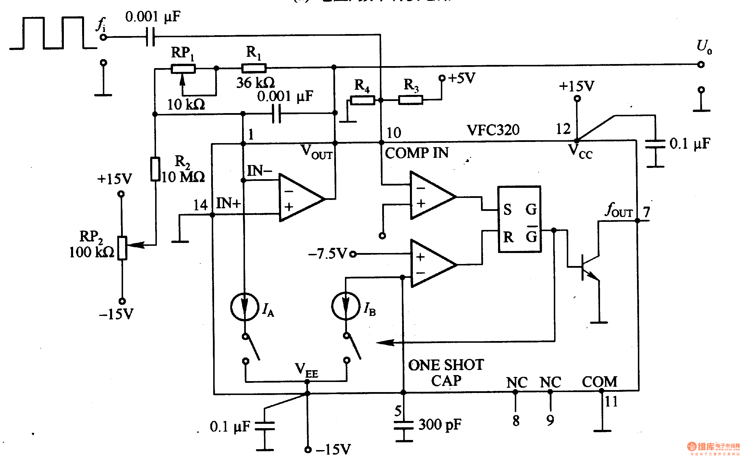
Figure 1-22 (a) illustrates a circuit that converts an input voltage of 0 to +10V (Ui) into a pulse with an output frequency ranging from 0 to 100kHz. In this configuration, pin 7 of the VFC320 is connected to...
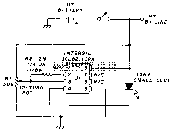
The precision voltage-monitor chip features a temperature-compensated voltage reference. Resistor R1 divides the battery voltage to align with the built-in reference voltage of IC1 (15 volts). When the voltage at pin 3 drops below 15 volts, pin 4 provides...
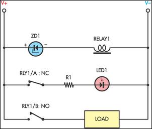
Sensitive low-current relay coils often operate at much lower voltages than their typical ratings. This can be undesirable in some applications, where low supply voltages can result in erratic system behavior. In some instances, this problem could be overcome...