
the designs of three phases SPWM variable frequency power supply of DSP
The variable frequency power supply can be categorized into direct and indirect variable frequency power supplies. The system studied in this text employs an indirect frequency conversion structure, which begins with a single-phase full-bridge rectifier to convert direct current into an SPWM waveform. This is followed by a final-stage smoothing circuit controlled by the DSP to produce a canonical sine wave. The frequency conversion system controller utilizes the TMS320F28335 digital signal controller, known for its high-speed processing capabilities at 150 MHz and its 32-bit floating-point processing unit. This advanced controller enhances performance by approximately 50% compared to previous generation digital signal processors while simplifying software development and maintaining compatibility with fixed-point C28x TM control device software.
The overall block diagram of the system includes several modules:
1. **Commutation and Filtering Module**: This module receives alternating current from the electrical grid, which is then commutated and filtered to provide a low-ripple direct current voltage for the converter.
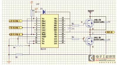
2. **Three-Phase Bridge Inverter Module**: This module converts the direct current voltage into alternating current. It employs intelligent Integrated Power Module (IPM) technology, characterized by simplicity and high reliability.
3. **Control Circuit Module**: This module measures the output voltage and current signals and generates SPWM control signals based on a specific control algorithm and strategy. It controls the switching of the IPM to maintain output voltage stability and manages the input voltage and current signals through an SPI interface. It also includes a frequency measurement unit for the outgoing signal.
4. **Voltage and Current Measurement Module**: To monitor the line voltage and phase current in real time, this module includes three voltage measuring circuits and three current detection circuits. All measurement signals are input to the A/D converter of the TMS320F28335 after isolation by a voltage follower.
5. **Auxiliary Power Module**: This module supplies the necessary direct current for the system's operation.
This comprehensive design ensures that the variable frequency power supply operates efficiently and reliably, meeting the demands of modern power systems.The variable frequency power supply, as the important constituent element of the power system, the quality of its characteristic concerns security and reliability index of the overall system directly. Such prominent advantages as the modern variable frequency power supply is succinct by low power consumption, high efficiency, circuit are favored.
The whole circuit of the variable frequency power supply is exchanged direct current exchange filter etc. and form partly, the output voltage and electric current waveform are pure sine waves, and frequency and range are adjustable within the specific limits.
This text has realized the design based on variable frequency power supply numerical control system of TMS320F28335, through the hardware resource on efficient use TMS320F28335 abundant slice, have realized the abnormality of SPWM is sampled, and adopt PID algorithm to make the system produce the high-quality sine wave, fast, such advantages as the high, flexibility of precision is good, system expansion ability is strong of having operation. On the basis of the structure, the variable frequency power supply can be divided into direct variable frequency power supply and big class of indirect variable frequency power supply two.
The variable frequency power supply that this text studies adopts the structure of indirect frequency conversion to be handed in promptly straight hand in the transformation procedure. Finish, hand in vary direct through single-phase full bridge rectifier at first, then convert direct current power supply to waveform, SPWM of three-phase, supply final-stage smoothing circuit until DSP control, form the canonial sine wave.
Frequency conversion system controller adopts the digital signal controller TMS320F28335 of first floating points of industry that TI Company introduces, it has 150MHz high-speed handling capacity, possesses the 32-bit microcomputer floating point processing unit, the totalizing operation of the 32-bit microcomputer of single instruction cycle, can respond to the request that employ and develop and integrate floating point processor characteristic of the advanced control device to the quicker code. Compared with previous generation`s leading digital signal processor, the latest F2833x floating controller not merely can promote the characteristic by 50% on average, still have with higher precision and simplifying software development, compatible fixed point C28x TM control device software characteristics.
The overall block diagram of system is shown as in Fig. 1. 1 Commutate the filtering module: The alternating current imported to the electric wire netting is commutated and filtered, offer the minor direct-current volts of ripple for converter. 2 Three-phase bridge inverter module: Vary the direct-current volts into alternating current. Among them the power level adopts the module of intelligent IPM power, the characteristic such as being simple, with high reliability of having circuit.
4 Controlling circuit module: After measuring the output voltage, electric current signal, produced SPWM control signal according to certain control algorithm and control strategy, go, control the intersection of IPM and make-and-break of gas switching tube to keep, export voltage stabilization, finish programme-controlled to look after to the intersection of input voltage and signal, the intersection of electric current and signal through the intersection of SPI and interface at the same time. Catch the unit and finish the frequency measurement of the outcoming signal. 5 The voltage, electric current measure the module: As requested, need to measure the changes of line voltage and phase current in real time, so need three-way voltage measuring and three-way electric current detection circuit.
All testing signals are input by A/D passway of TMS320F28335 after the voltagefollower is isolated. 6 Auxiliary power module: Offer the direct current p 🔗 External reference
Related Circuits
This circuit is a Power Amplifier designed to deliver an output power exceeding 600 Watts for speakers with an impedance of 4 Ohms. The high-power amplifier circuit utilizes six n-channel MOSFETs in the output stage, which alone provides approximately...
The direct coupling audio power amplifier utilizes an integrated operational amplifier. There are typically two practical configurations. The first configuration, depicted in (a), features a circuit structure that includes the output of the operational amplifier and a complementary symmetry...
Al's positive input is biased by the thermocouple. Al's output drives a basic voltage-to-frequency (V-F) converter, which consists of 74C04 inverters and related components. Each V-F output pulse results in a fixed amount of charge being transferred from a...
The diagram illustrates the circuit of a versatile USB power socket that safely converts 12V battery voltage into a stable 5V output. This circuit enables the use of various USB-powered devices. The circuit design consists of several key components to...
When the input voltage is between 198-242V, the average load current should be maintained at 0.5-1A, and the output voltage must remain at 15V with an error margin of less than 5%. The design and measurement of the stabilized...
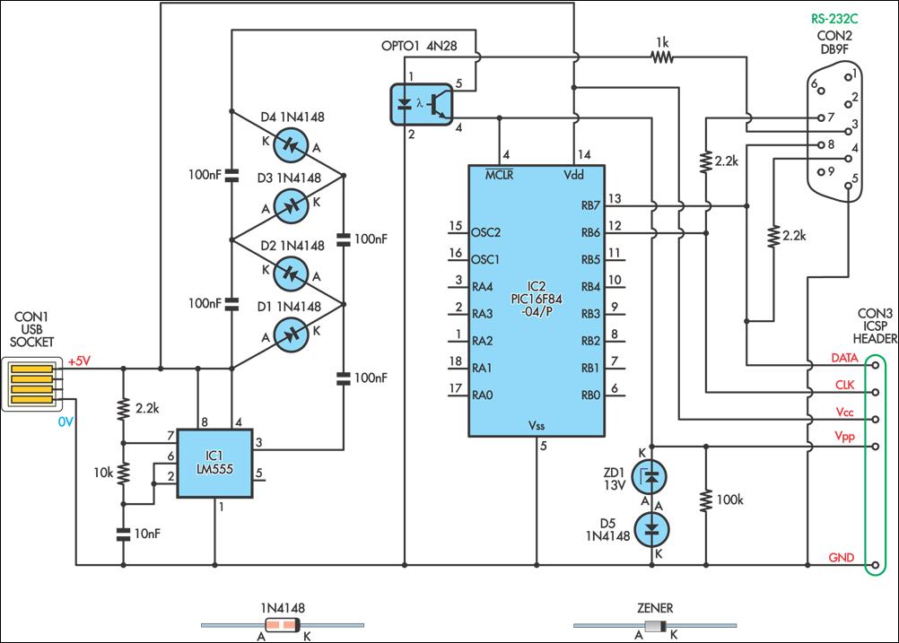
This simple circuit can be used to program the PIC16F84 and similar flash memory type components. It utilizes a 555 timer integrated circuit (IC) to generate the programming voltage from a +5V power supply, enabling operation from a computer's...