
power supply How do I select the accompanying components for an optocoupler

The circuit design incorporates an optocoupler (MOC3021) to isolate the high-voltage AC mains supply from the low-voltage microcontroller circuit. The MOC3021 is specifically chosen for its ability to drive a triac, which is essential for controlling AC loads. The circuit's operation is based on the principle of current transfer ratio (CTR), which defines the relationship between the input current through the optocoupler's LED and the output current through the phototransistor.
In the design, R1 is calculated to limit the current through the optocoupler's LED to approximately 1mA, ensuring proper activation of the phototransistor. The resistor value is critical, as it directly affects the CTR and, consequently, the output signal's reliability. The chosen resistance of 39kΩ for R1 will ensure that the LED operates efficiently within the specified range, while also accommodating variations in mains voltage.
R2 serves as a pull-up resistor connected to the output of the phototransistor. This resistor is essential for defining the high state of the output signal when the phototransistor is not conducting. The value of R2 should be selected with consideration to the voltage drop across it, ensuring that the output voltage remains above VIL(max) when the load is off. Adjusting R2 to a higher value, such as 10kΩ, may help achieve the desired low output voltage when the load is on.
The relay in the circuit acts as a switching device to control the load based on the microcontroller's output. The microcontroller will monitor the state of the load through an interrupt, enabling it to respond promptly to changes in the load state. The integration of these components allows for a robust and reliable method of sensing and controlling the state of an electrical appliance, ensuring safe operation while maintaining the necessary isolation between high and low voltage sections of the circuit.
Overall, careful selection of resistor values and understanding of the optocoupler's behavior in conjunction with the microcontroller's voltage thresholds are critical to the successful implementation of this circuit.Using an optocoupler ( MOC3021 ) to sense the On/Off state of an electrial appliance using a microcontroller ATmega16L. How do i go about doing this My mains supply specs are 230V, 50Hz. How do I design the surrounding circuit and select component values, like the resistors Referring to the above schematic.
The idea is to use this circuit to determine whether the load is on or off. The output pin from the optocoupler connects to an external interrupt of the Microcontroller I`m using which is ATmega16L. The interrupt will Monitor the state of the load. After monitoring I can toggle the state of the load using a relay (relay acts as a Control mechanism) which connects to the same microcontroller.
Now, I tried calculating the resistor values for R1, R2 and Rc. Note, microcontroller`s VIL(max) = 0. 2xVcc = 660mV and VIH(min) = 0. 6xVcc = 1. 98V and VIH(max) = Vcc+0. 5 = 3. 8V. To calculate Rc is quite easy. When the transistor is not conducting the output is high (at 3. 3V). When the transistor conducts the output is pulled low. so from microcontroller`s point of view, output high means load is switched OFF and output low means load is switched ON. Looking at the datasheet for SFH621A-3, using 34% minimum CTR at IF = 1mA. Therefore, at 1mA input, the output is going to be 340uA. So in order for the microcontroller to detect low voltage from the output of the optocoupler can I use resistor value of 1Kohm So that the output from the optocoupler will have a voltage of 340mV (which is below VIL(max) Aim: the aim is to keep the LEDs ON* for maximum period of time in a 10mS half period (20mS full period of 50Hz).
Lets say LEDs have to be ON for 90% of the time, that means LEDs require at least 1mA of current for 90% of the time for that half period which means LEDs will be active for 9mS in a 10mS half period. So, 9mS/10mS = 0. 9 * 180(half period) = 162 degrees. This shows the current will be 1mA between 9deg and 171deg (and less than 1mA from 0deg to 9deg and 171deg to 180deg).
Did not consider ON time to be 95% as working with whole numbers is neat and 5% doesn`t make any difference not in this application at least. So, R1 ‰¤ (47. 8V - 1. 65V) / 1mA = 46. 1 Kohms Choosing a value one smaller than 46. 1 Kohms of 39 Kohms (e12 series). Now that a smaller value resistance is chosen compared to what was calculated, means current through the diodes will be greater than 1mA.
Now, after all this the initial CTR was 34% which means 1mA in will be 340 µA out. But now because of 2x22 Kohm resistors the current will be slightly more on the output. That means higher potential across the pull up resistor Rc. Would there be an issue to get a volt drop below 500mV on the output of the optocoupler David, please add some information about yourself on your profile. Like Olin always says that`s not for you, that`s for us. It helps us to assess your level of knowledge so that we can answer appropriately. stevenvh Jun 3 `12 at 6:13 Re your edit: a 1k resistor will have 340 mV across it (Ohm`s Law). So the output voltage will still be 3. 3 V - 340 mV = 3 V. You have to go lower than VIL(max) if you want the uC to see it as a low. So increase the 1k, for instance to 10k. Then the voltage across the resistor will be 3. 4 V theoretically, but limited to the power supply, and the output will be 0 V. stevenvh Jun 13 `12 at 9:43 The MOC3021 is an optocoupler with a triac output. It`s used to drive a power triac typically to switch mains operated appliances. Triacs can only be used in AC circuits. The two LEDs in antiparallel ensure that the transistor is activated on both half cycles of the mains.
Many optocouplers only have 1 LED, that would work, but give you an output pulse of 10ms in a 20ms period for 50Hz. You would need to place a diode in antiparallel to the input also in that case, to protect the LED from overvoltage when reverse polarized.
Important is CTR or Current Transfer Ratio, wh 🔗 External reference
Related Circuits
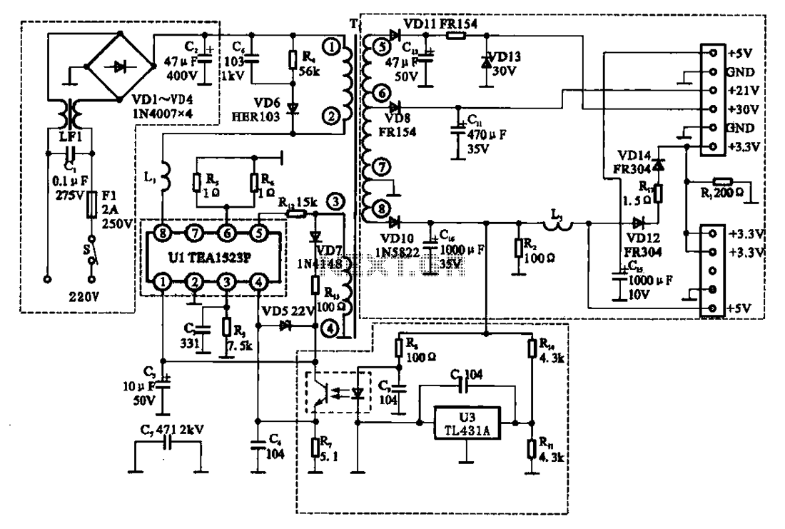
The East Shi IDS-2000F STB switching power supply circuit primarily consists of an AC input circuit, a switching oscillation circuit, an output circuit, and a secondary steady voltage control circuit. The AC input circuit includes a switch (S), fuse...
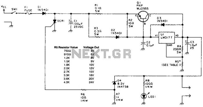
A laptop computer power supply that provides a 9-V output, includes crowbar overvoltage protection, and operates from a 12-V input supply is described. The input supply voltage must be at least 3.6 V above the desired output voltage. The...

A simple lab power supply electronic project can be designed using this circuit diagram, which is based on the LM2576 monolithic integrated regulator that provides all the active functions for a step-down (buck) switching regulator. As seen in the...
The power supply terminal should utilize a 1 µF chip capacitor filter, positioned as close as possible to the chip's supply pin. The signal is generated by the input pins 2 and 3. The source resistance of the signal...
With the increase in the variety of modern electrical equipment for vehicles and the rise in power levels, there is a growing demand for different types of power supplies, including AC and DC sources. The power system needs to...
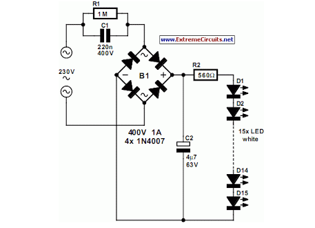
An array of white LEDs can serve as an effective small lamp for the living room. LED lamps are commercially available. LED arrays are increasingly popular for providing ambient lighting in residential spaces. The use of white LEDs in a...