
Many simple door buzzer sound circuits
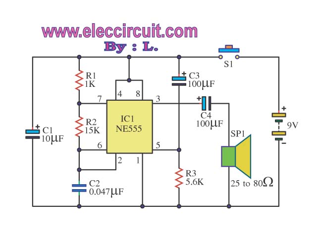
The Door Buzzer circuit is a straightforward yet effective electronic design that leverages the capabilities of the NE555 timer IC for sound generation and the LM386 audio amplifier for sound amplification. The NE555 timer operates in astable mode, producing a square wave output at pin 3, which mimics the ringing of a doorbell. The frequency of this output can be adjusted using the resistor R1 and the three potentiometers (VR1, VR2, VR3). Each potentiometer allows for individual control over the tone and volume, enabling the user to customize the sound to their preference.
The LM386 amplifier is connected to the output of the NE555 to boost the audio signal before it drives the speaker. This configuration ensures that the sound produced is loud enough to be heard clearly at a distance, making it suitable for a doorbell application. The choice of a loudspeaker with an impedance between 25-80 ohms ensures compatibility with the LM386 output, which is designed to drive such loads efficiently.
The circuit is powered by a 9V battery, providing a suitable voltage level for both the NE555 and the LM386. The requirement for a dual power supply with positive, ground, and negative connections allows for stable operation and minimizes noise in the audio output. Overall, this circuit is an excellent choice for those looking to create a simple and effective doorbell system with customizable sound features.Door Buzzer by use, IC 555. Perform sound electric bell origin. When press S1 as a result have a voice fair loud. This circuit almost must not do anything. Because divisible Amen! should use 25-80ohm size loudspeakers. will make good sound use force against electricity low work or economize the electricity. You will may use 9V batteries all right sir. Someday I goes to visit a friend. He begs me helps to seek electric bell front door circuit. In model to be simple, use the a little equipment. I then choose the Door Buzzer circuit this give. Because of use, IC NE555 produce electric bell sound and use IC LM386 for amplify talk at one time. For R1 use fine decorate the sound as you like it. request have fun this circuit. This is a basic electronic ell circuit, it is interesting. We use a number of IC-741 Op-amp, it works. When you press S1 will be mimic the bell sound at the output pin 6 of IC1, which we can fine tone sound with three potentiometer are VR1-1M, VR2-1M and VR3-1M to control sound as close as possible. We set form of the audio oscillator generator or sine wave form can be changed with by pressing our S1.
But sound is slight required to use power amplifier for boost up its. And this circuit need the dual power supply positive, ground, and negative 9V power supply. 🔗 External reference
Related Circuits
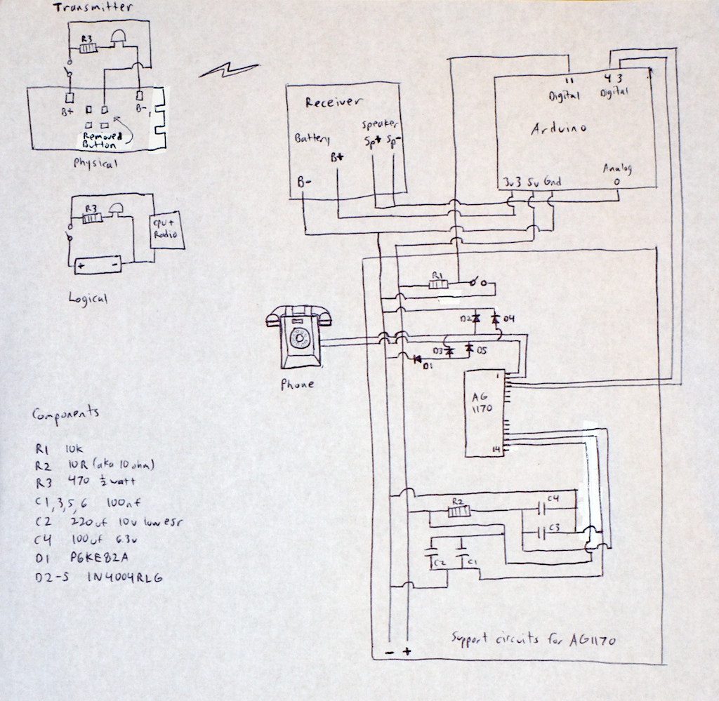
Any phone can be utilized for this project, so there is no need to worry about obtaining the same model as mentioned. If an antique Bakelite phone is chosen, basic restoration steps include cleaning it with a rag dampened...
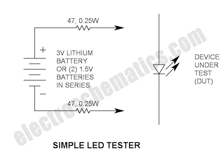
Do not let its extreme simplicity deceive you — this device is useful! Many have been made over the years, and some have even been given away as gifts. Yes, multimeter... A multimeter is an essential instrument in electronics, used...
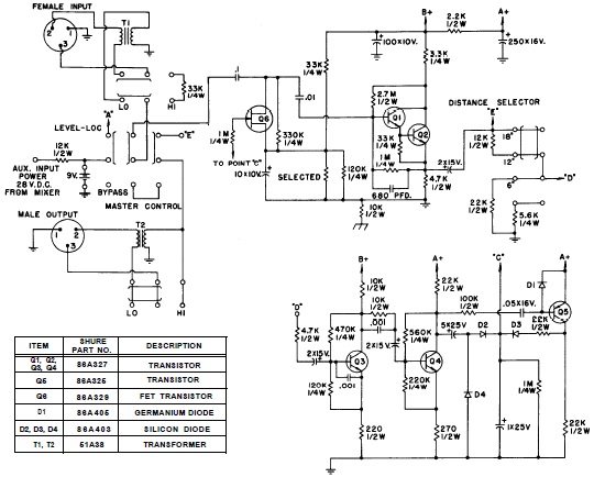
SHURE is an American corporation that manufactures consumer and professional audio electronics, including microphones, phonograph cartridges, and discussion systems. SHURE Incorporated is a well-established entity in the audio electronics industry, recognized for its innovative design and high-quality products. The company...
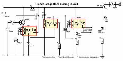
Timer garage door circuit schematic diagram, printed circuit board. The timer garage door circuit is designed to automate the opening and closing of a garage door based on a predetermined time interval. The schematic diagram illustrates the layout and connections...
Normally, an analog-to-digital converter (ADC) requires interfacing through a chip to convert analog signals into digital format. This necessitates both hardware and software, resulting in increased complexity and overall cost. The circuit presented here is configured around the ADC...
The timer is utilized in a conventional setup, with the exception that the timing resistor has been substituted with a current source derived from the operational amplifier DA1 (741). This modification enables the achievement of excellent linearity, exceeding 3%....
Warning: include(partials/cookie-banner.php): Failed to open stream: Permission denied in /var/www/html/nextgr/view-circuit.php on line 713
Warning: include(): Failed opening 'partials/cookie-banner.php' for inclusion (include_path='.:/usr/share/php') in /var/www/html/nextgr/view-circuit.php on line 713