
Vox box
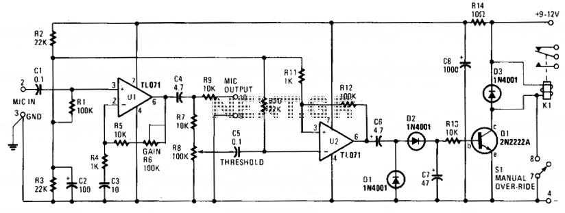
The circuit design begins with the microphone preamplifier (U1), which serves to amplify low-level audio signals captured by the microphone. The gain of this preamplifier can be adjusted using the THRESHOLD control (R8), setting a specific voltage level that must be exceeded for the subsequent stages to activate.
The Schmitt trigger (U2) functions as a voltage comparator with hysteresis, providing a stable output that prevents noise from causing false triggering. When the input voltage from the preamplifier exceeds the threshold, U2 rapidly transitions to a high output state, ensuring a fast response time for the circuit.
Following this, the output from U2 is rectified, typically using a diode, which allows only the positive half of the waveform to pass through. The rectified voltage is then stored in capacitor C7, which smooths out fluctuations and provides a stable voltage to drive the relay energizer transistor (Q1).
Once Q1 is activated by the voltage across C7, it allows current to flow through the coil of relay K1. This relay is configured as a Single Pole Double Throw (SPDT) switch, enabling it to either complete or break an external circuit, depending on the state of the relay. The relay can control various loads, including AC or DC devices, making this circuit versatile for applications such as voice-activated control systems or automated switching devices.
In summary, the VOX Box circuit effectively processes audio signals, converting them into control signals that can manipulate external devices through relay switching, showcasing a practical application of basic electronic components in signal processing and control.The electronic circuit in the VOX Box consists of three parts: a microphone preamplifier, a Schmitt trigger, and a relay driver. Input signals (MIC INPUT terminals) to the microphone preamplifier (Ul) are amplified and fed to a THRESHOLD control (R8).
When the preselected threshold voltage level is exceeded, the output of the Schmitt trigger (U2) immediately goes high. The signal from U2 is rectified and the voltage developed across C7 turns on the relay energizer transistor (Ql).
That transistor action passes pull-down current through the coil of relay Kl. The changing of the relay SPDT contacts can be used to either make or break an external ac or dc circuit. 🔗 External reference
Related Circuits
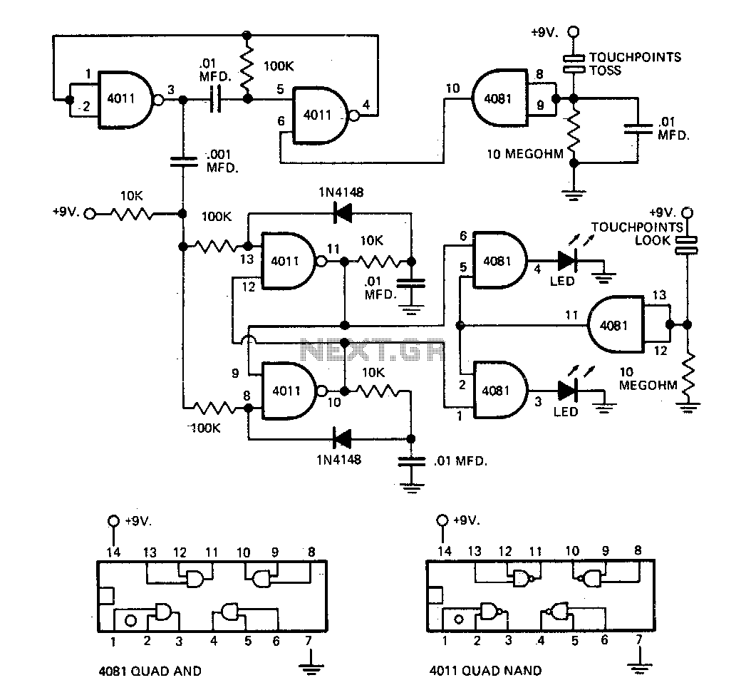
The circuit employs an astable multivibrator to alternate between heads and tails conditions, while a flip-flop is utilized to retain the state determined by the multivibrator. As a result, the circuit is designed so that the flip-flop's state changes...
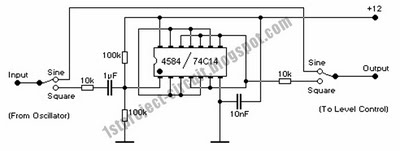
Prior to emailing Pablo Gian Villamil, he provided a link to his class notes on generating polyphonic sound with Arduino. Efforts were made to understand his circuitry through various blog posts and component listings, including the CMOS Hex Schmitt...
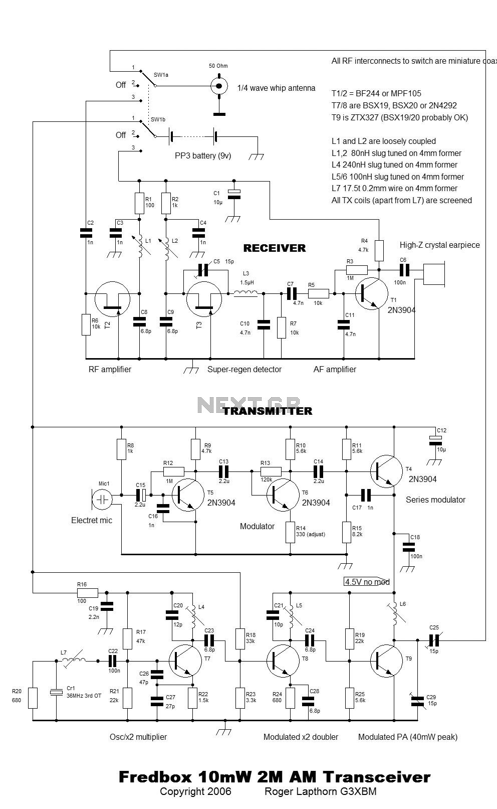
This is the story of the Fredbox, a rig that first originated in 1974 in Cambridge. Recently, it has been restored to full working order to capitalize on the renewed interest in AM operation on 2m in the UK....
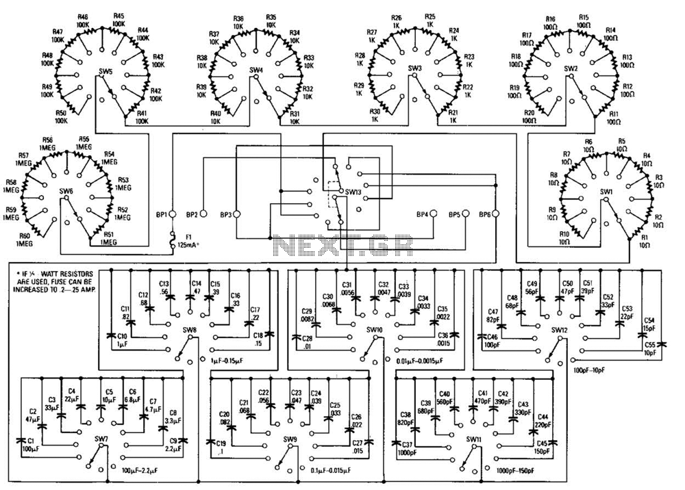
This decade box can be configured for any resistance value between 10 and 11.1 in 10-stop increments. A switch is employed to set various RC configurations. It is recommended to utilize precision components in the circuit. If feasible, verify...
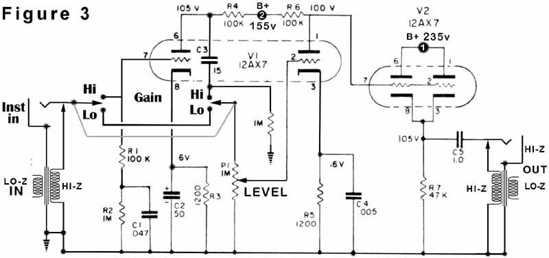
V1 and V2 are 12AX7 dual triodes. Each half of V1 is configured as a Class A voltage amplifier in a Common Cathode arrangement. In contrast, both halves of V2 are connected in a Cathode Follower configuration to provide...
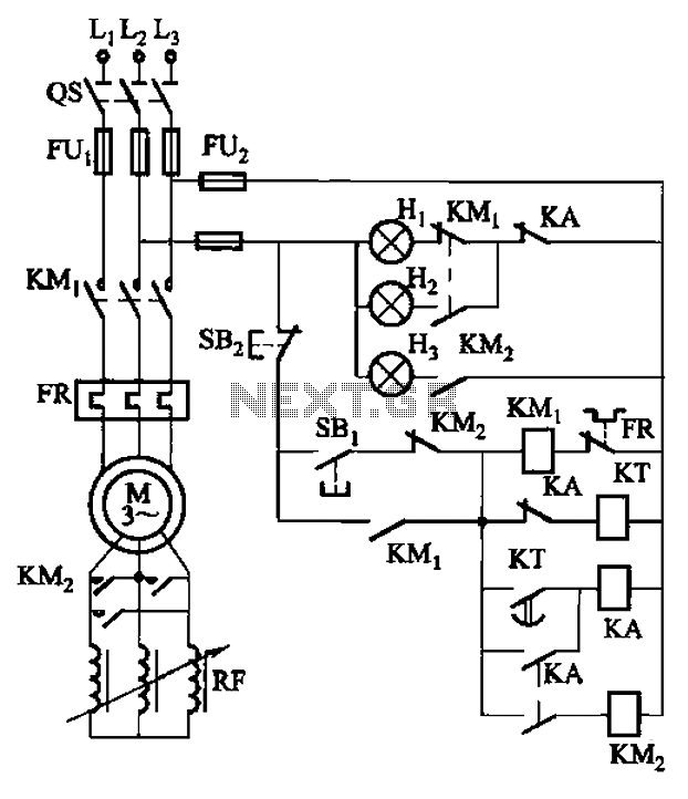
The circuit depicted in Figure 3-165 utilizes a time relay (KT) for controlling the start-up time. Indicator light Hi serves as the power indicator, H2 is designated for the start lights, and H3 functions as the running lights. The circuit...