
3 band equalizer circuit
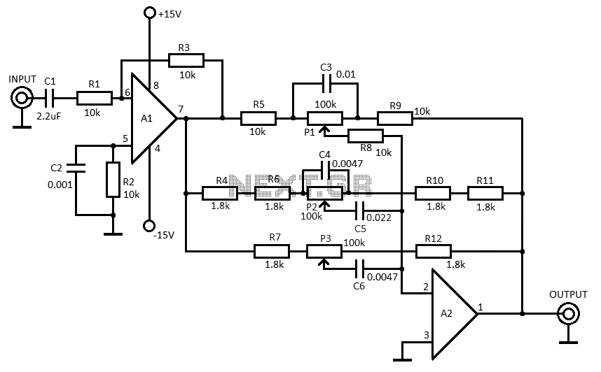
The 3-band equalizer circuit employs the LM833 op-amp to create three separate filter stages, each tailored to enhance or attenuate a specific frequency range. The bass filter typically operates within the range of 20 Hz to 250 Hz, the midrange filter covers approximately 250 Hz to 4 kHz, and the treble filter is effective from 4 kHz to 20 kHz. Each filter stage can be adjusted using potentiometers, allowing for precise control over the audio output.
The circuit configuration involves using resistors and capacitors to set the cutoff frequencies for each band. The feedback network around the LM833 op-amp is designed to provide the desired gain and frequency response. For instance, the bass filter can be configured with a higher gain to amplify low frequencies, while the treble filter can be set with a lower gain to avoid distortion of high frequencies.
Power supply considerations for the LM833 op-amp should include a dual supply voltage, typically ±15 V, to ensure optimal performance. Proper decoupling capacitors should be placed close to the power pins of the op-amp to minimize power supply noise and enhance stability.
Additionally, the output of each filter stage can be mixed together using a summing amplifier configuration, allowing the user to achieve a balanced overall sound. Careful layout of the circuit board is essential to minimize interference and maintain signal integrity, particularly in high-frequency applications. Overall, this 3-band equalizer circuit provides a versatile solution for audio signal processing, enabling users to tailor their listening experience to personal preferences.This 3 band equalizer circuit is an active filter network for bass, mid and high audio ranges. It is designed around the LM833 opamp from National Semiconductors. This opamp IC has the following charactersistics: very low noise figure, wide.. 🔗 External reference
Related Circuits
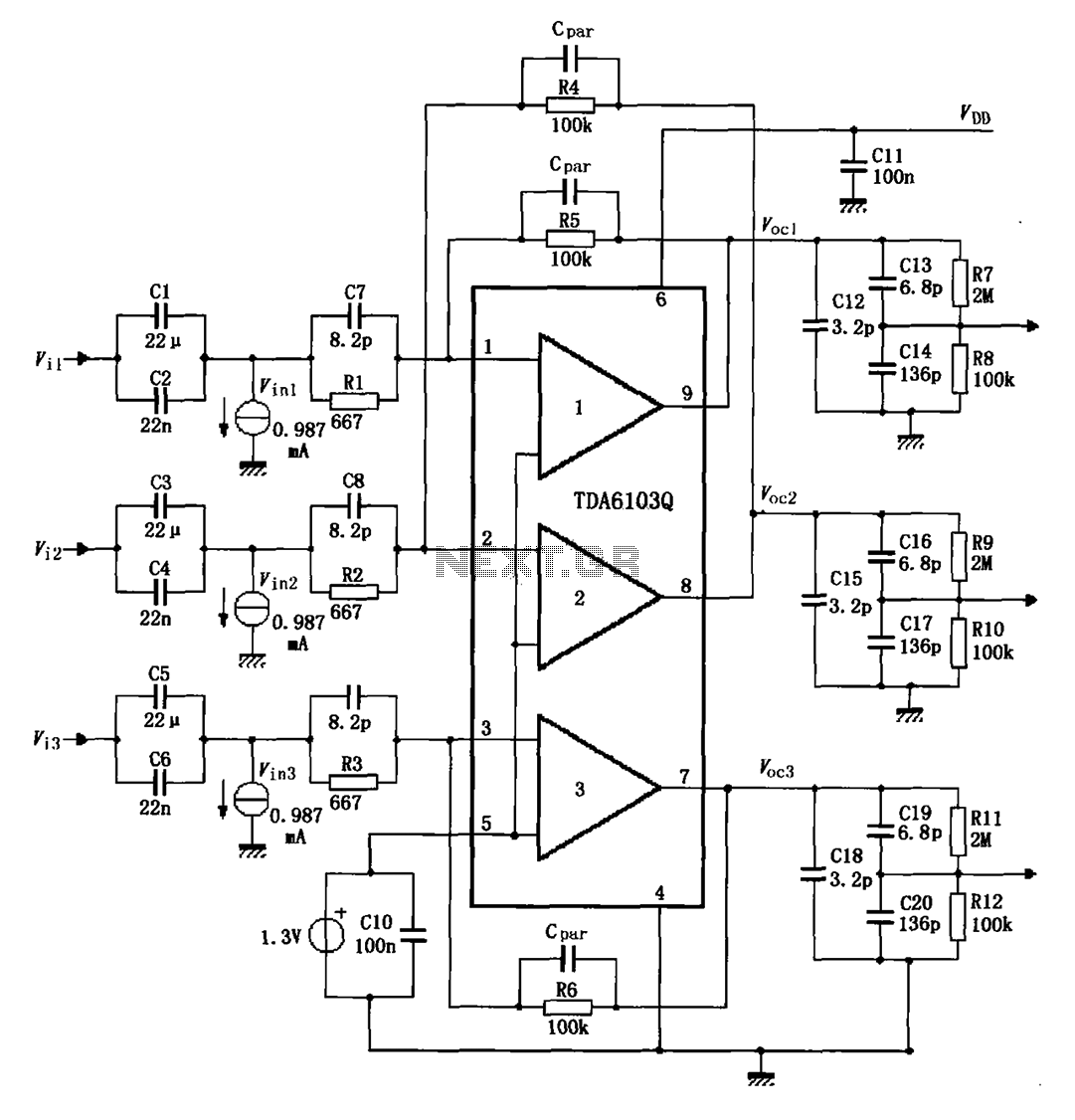
The TDA6103Q test circuit features a feedback factor of 1/150. Input signals Vi1, Vi2, and Vi3 are directed through an input resistor network that includes capacitors to the TDA6103Q pins 1, 2, and 3, which are part of the...
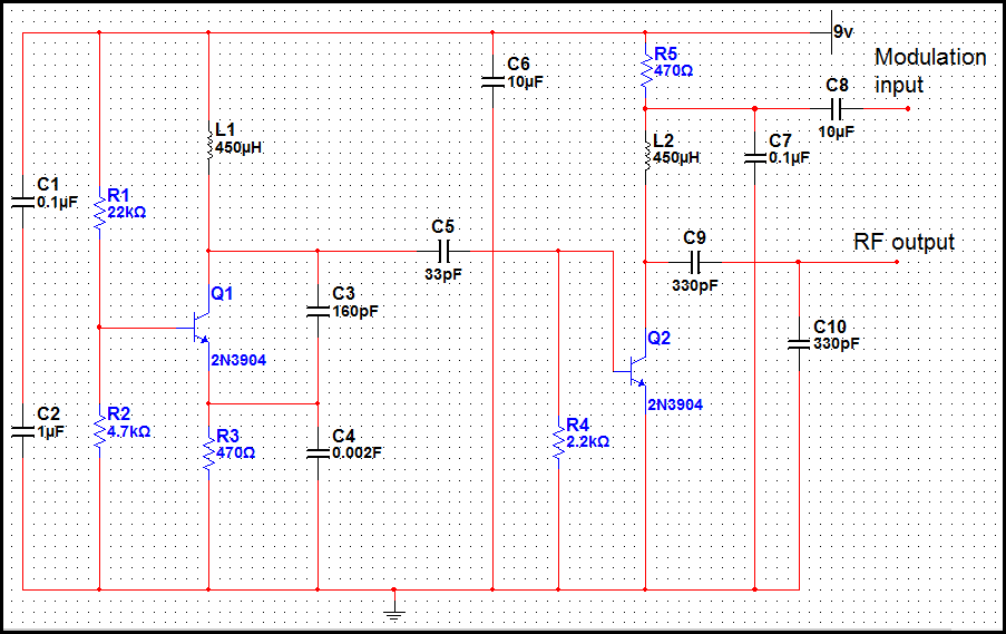
The transmitter operating at 2 meters (144 MHz) was primarily designed for use by radio amateurs as a radio beacon. It generates a high-quality signal suitable for this purpose. The 2-meter transmitter circuit typically includes several key components to ensure...
This page will be updated as material becomes available. This new system will essentially replace the original BCD design, which was created by WB6IGP and N6IZW and was featured in the ARRL UHF/Microwave Project Manual. Their work was later...

A dimming control circuit generates a dimming control signal to determine the brightness of at least one light-emitting diode. The dimming control signal consists of multiple bright-dark cycles, each comprising a bright phase and a dark phase. The bright...
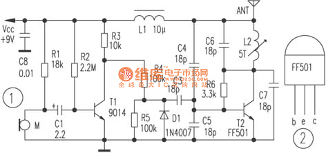
The circuit depicted utilizes a specialized launch tube T2 along with its associated components to create a high-frequency oscillator operating within the frequency range of 88 to 108 MHz. An electret microphone captures the audio signal, which is subsequently...
Most 24V power systems in trucks, 4WDs, RVs, boats, and similar applications utilize two series-connected 12V lead-acid batteries. The charging system is capable of maintaining the total voltage of the individual batteries. If one battery is experiencing failure, this...