
Single-phase full-wave rectifier circuit 02 phase
The closed-loop control system described integrates a variety of components to achieve precise motor speed regulation. The stepping motor CNC system's control circuit initiates the process by issuing commands that are detected by the receiver. The phase-sensitive rectifier plays a crucial role in this system by converting the received AC signal into a DC signal, which is essential for accurate control of the motor's operation.
The operational amplifier is pivotal in modulating the conduction angle of the thyristor, which in turn alters the voltage supplied to the three-phase AC induction motor. This alteration changes the strength of the rotating magnetic field, enabling smooth and continuous speed adjustments of the motor. The integration of a tachometer generator for negative feedback is critical for maintaining system stability and enhancing the precision of the motor's performance.
The longitudinal and horizontal AC motors drive the feed screw, facilitating the lathe's operational movements. The design of the phase-sensitive rectifier is particularly noteworthy, as it comprises both a transmitter and a receiver winding that work in tandem to ensure accurate phase detection. The use of a 110V AC supply voltage allows the system to establish a reference angle, which is necessary for determining the angular displacement of the transmitter rotor.
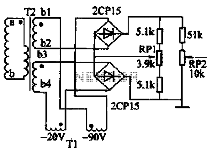
In equilibrium, the system is designed to output zero voltage, indicating that there is no error. However, any deviation from this equilibrium produces a voltage signal that can be processed to correct the error. The single-phase full-wave phase-sensitive rectifier circuit operates effectively by alternating between two groups, allowing for consistent voltage output while utilizing resistive components to maintain balance.
Overall, the system's architecture is designed to provide precise control over the motor's speed, ensuring that the lathe operates efficiently and accurately, with mechanisms in place to adjust for any discrepancies in performance. Closed loop portion is composed of longitudinal and transverse two systems, circuit works briefly as follows: issued by the control circuit of the stepping motor CNC system pav ilion order, the receiver receives the signal, by phase-sensitive rectifier into a DC signal, and then by the operational amplifier, control thyristor conduction angle, the voltage is changed from the three-phase AC induction motor supplier given taro winding, which changed the rotating magnetic field strength, to achieve a stepless adjustment of the motor speed. In order to make the system stable operation, improve the precision and mechanical properties of hardness, it introduced tachometer generator (cs) speed of negative feedback.
Longitudinal (Z) l.lkW and horizontal (X) 550w AC motor drive for the feed screw turning movement, so the lathe work. 2) phase-sensitive rectifier: a transmitter (FZ) winding and a receiver (sz) three-phase windings connected to one correspondence.
110V AC supply voltage transmitter see magnetic windings, that is the initial angle of the receiver at both ends of the stator winding output voltage and phase reflect the transmitter rotor angular displacement hatred that reflect the magnitude and direction of the error angle between the transmitter. At equilibrium, the output voltage is zero, otherwise, an error occurs, a voltage signal output. Figure 2-28 is a single-phase full-wave phase-sensitive rectifier circuit, the two groups work alternately, respectively, in the resistance 5.lk voltage output, RP1 is used to adjust the balance.
The rectified AC into a DC signal, the speed loop RP2 sent to the operational amplifier (ST) llr cream A-side to zoom.
Related Circuits
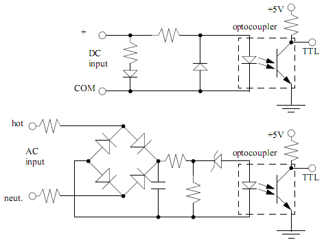
PLC input cards typically do not provide power, necessitating an external power supply for inputs and sensors. An example of an input card and a ladder logic diagram illustrates how to connect an AC input card. The PLC inputs...
The SheevaPlug is known to have a suboptimal power supply, particularly affecting users in the UK operating at 240VAC. Additionally, heavy loads on the USB can cause issues, especially when connecting an external mechanical disk drive. This project aims...
With a 1.5V battery supply, the integrated circuit LM3909 can drive the light-emitting diode NSL5027. The 300μF electrolytic capacitor acts as a timing capacitor, which limits the flash speed to approximately 1Hz. The circuit utilizes the LM3909, a popular LED...
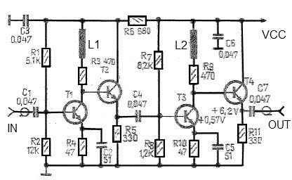
A simple and effective antenna amplifier can be built using the provided circuit diagram. This amplifier is designed for the frequency range of 35 kHz to 150 MHz. It utilizes transistors, offering a low non-linearity of 3 dB and...
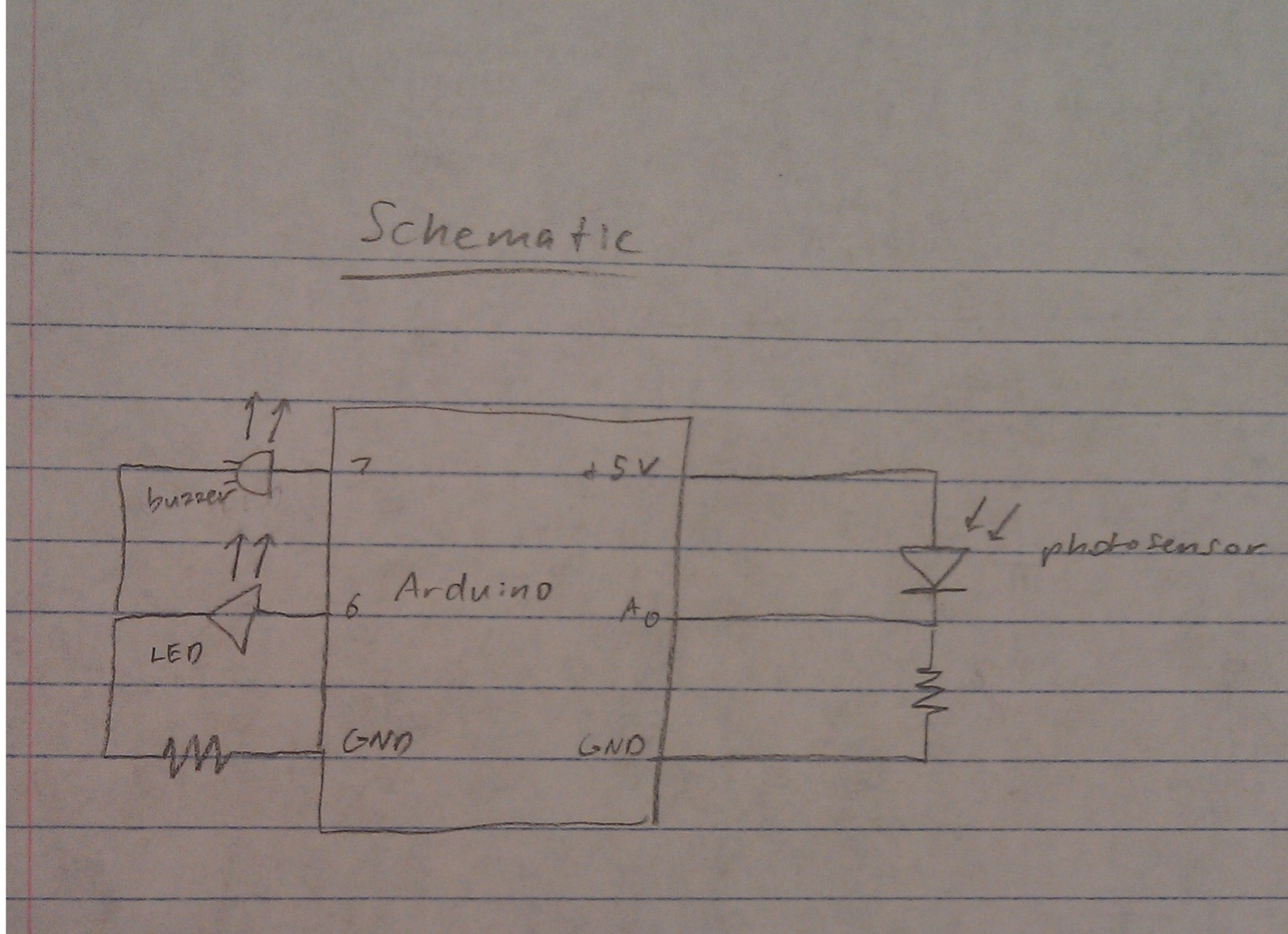
A nightlight combined with a wake-up alarm has been developed. This nightlight incorporates six LEDs that activate when a photosensor detects low ambient light levels. Additionally, a buzzer plays a cheerful tune when ambient light levels increase again. The...
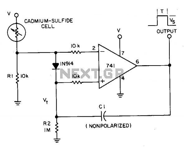
A photocell circuit provides automatic threshold adjustment. Monostable action prevents undesired retriggering of the output. With only one op amp IC, the circuit offers automatic adjustment of its trigger level to accommodate various light sources, changes in ambient light,...
Warning: include(partials/cookie-banner.php): Failed to open stream: Permission denied in /var/www/html/nextgr/view-circuit.php on line 713
Warning: include(): Failed opening 'partials/cookie-banner.php' for inclusion (include_path='.:/usr/share/php') in /var/www/html/nextgr/view-circuit.php on line 713