
Wah pedal for Guitar

More: I wired the 1M resistor direct on the circuit board, and carefully removed the .01uF capacitor and 33K resistor, wiring a 10K resistor soldered at one end only. This is really quite shabby, but given that its all enclosed, has been reliable.
Equally shabby, the 1M resistors are located on the back of the switch, with the 3 capacitors wired at one end on the switch and all wired together at the other end. Using caps with solid wires this is really quite strong, but doesn't look good, and would not pass any serious quality inspection.
Nevertheless, its a foot pedal, and gets kicked around, and it still works. I should admit that despite this new flexibility, 95% of the time I use the standard settings.
Replace the 33K resistor across the coil with a 10K resistor in series with a 50K Linear pot. When this pot is centred, the standard value is restored. Switch different value capacitors for the standard 0.01 value at one end of the coil. Increasing this value 4 times decreases the frequency range by a factor of 2. There are some suggested values on the circuit for a 5-way switch, where the centre position is standard. The 1M resistors prevent a loud popping sound when you turn the switch. Replace the SPDT footswitch with a DPDT switch and wire it as above for a true bypass switch. Note the addition of a 1M resistor on the input switch.
A compact circuit board design is suggested for integrating additional components into the existing foot pedal. The board should be securely mounted within the casing to ensure stability during operation. The resonance control is implemented using a potentiometer, which should be positioned conveniently for user access. A three-position ON-ON-ON mini-toggle switch is employed to select among three frequency ranges, providing versatility in sound modulation. This switch, being compact, is designed to fit behind the socket, but careful consideration of dimensions is necessary if opting for a rotary switch instead.
The circuit modification includes direct soldering of a 1M resistor on the circuit board, while altering the configuration of capacitors and resistors. The original .01uF capacitor and 33K resistor are replaced with a single 10K resistor, enhancing the circuit's functionality, albeit with a less refined appearance. The arrangement of resistors and capacitors on the switch must ensure strong connections, particularly those utilizing solid wire components, while acknowledging that aesthetic quality may be compromised.
The design supports a standard operation mode, with the option to adjust settings as needed. A 10K resistor is placed in series with a 50K linear potentiometer to facilitate variable resistance, allowing users to revert to standard values when the potentiometer is centered. The frequency range can be modified by switching capacitors, with the potential to halve the frequency range by increasing the capacitance value.
To enhance the pedal's functionality, replacing the single-pole double-throw (SPDT) footswitch with a double-pole double-throw (DPDT) switch is recommended. This modification enables true bypass functionality, ensuring that the signal path remains unaltered when the effect is disengaged. An additional 1M resistor should be incorporated into the input switch configuration to mitigate any unwanted noise during operation.The right way to do this is with a small extra pc board to accommodate the new components, firmly secured inside the case, and wired carefully and neatly. Unfortunately, I did none of these things, but it worked reliably and if it ain't broke. I used a pot for the resonance control mounted just forward of the socket on the side of the case, and I used a three position ON-ON-ON mini-toggle (these can be wired as a single pole, 3 way switch) for three frequency ranges.
This switch is small and fits behind the socket. You could use a rotary switch, but you need to be sure it fits in the case, of course. I wired the 1M resistor direct on the circuit board, and *carefully* removed the .01uF capacitor and 33K resistor, wiring a 10K resistor soldered at one end only. This is really quite shabby, but given that its all enclosed, has been reliable. Equally shabby, the 1M resistors are located on the back of the switch, with the 3 capacitors wired at one end on the switch and all wired together at the other end.
Using caps with solid wires this is really quite strong, but doesn't look good, and would not pass any serious quality inspection. Nevertheless, its a foot pedal, and gets kicked around, and it still works. I should admit that despite this new flexibility, 95% of the time I use the standard settings. Replace the 33K resistor across the coil with a 10K resistor in series with a 50K Linear pot. When this pot is centred, the standard value is restored. Switch different value capacitors for the standard 0.01 value at one end of the coil. Increasing this value 4 times decreases the frequency range by a factor of 2. There are some suggested values on the circuit for a 5-way switch, where the centre position is standard.
The 1M resistors prevent a loud popping sound when you turn the switch. Replace the SPDT footswitch with a DPDT switch and wire it as above for a true bypass switch. Note the addition of a 1M resistor on the input switch. 🔗 External reference
Related Circuits
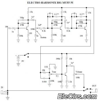
The Electro Harmonix Big Muff Pi circuit would likely benefit from the incorporation of a modern input-jack power connection and a DPDT bypass switch. The specific types of transistors and diodes used in the circuit are not specified. It...
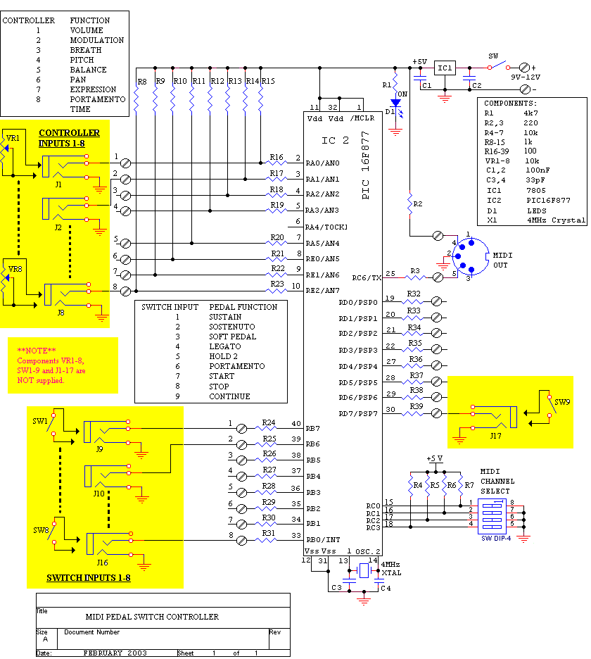
The sustain pedal, also known as the damper pedal, sends a controller value of CC64 when operated. Pressing the pedal results in an output value of 127, while releasing it results in an output value of 0. Tone generators...
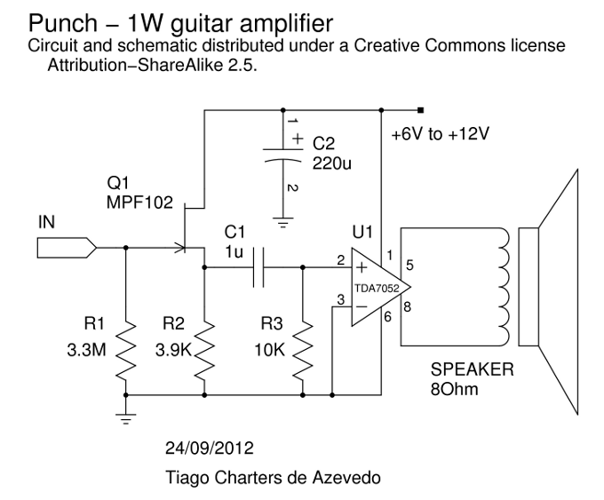
An alternative to the well-known ROG Ruby amplifier, this design shares a similar topology, featuring a buffer and a chip amplifier. It employs a JFET buffer utilizing the MPF102, along with the 1W TDA7052 chip. The amplifier delivers a...
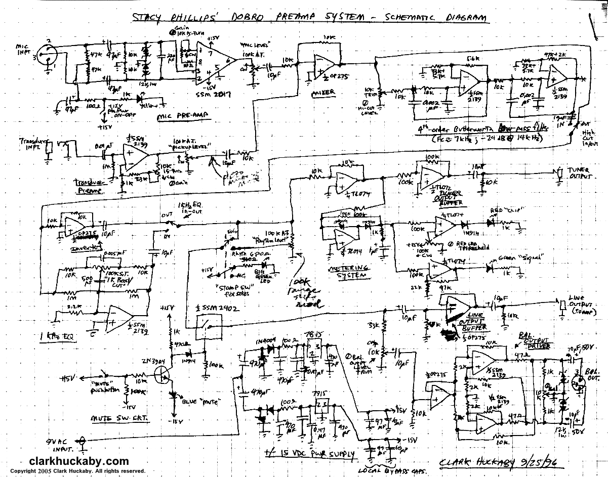
A stomp-box was designed and built for Grammy-winning resophonic guitar player Stacy Phillips. He typically uses two transducers on his Dobro-style instruments: a piezo element mounted internally and a gooseneck-mounted electret microphone positioned approximately one inch above the resonator...
This is a versatile distortion pedal. Think of it as analogue modelling, using analogue circuitry to model a wide range of analogue distortion devices. It includes the main elements found in the majority of distortion boxes. The unit comprises...
Even with the controls set to their maximum position, there will always be some signal leakage, resulting in a loss of tone. With Module 3, engaging the bypass switch to 'Solo' disconnects the tone and volume controls from the...