
Guitars Modulator

The described circuit involves a bypass feature that enhances the tonal characteristics of the instrument by allowing the pickups to connect directly to the output jack, bypassing any tone or volume modifications. This configuration is particularly beneficial for achieving a richer sound, especially from the neck pickup. The standard Modulator jack socket serves as the output interface, capable of stereo output by utilizing separate channels for each pickup.
The design of Module 3 and its close variant is an intricate task, where only a minor alteration in wiring distinguishes them. The stereo output mechanism relies on a careful arrangement of the signal paths, ensuring that the neck pickup feeds into one channel while the bridge pickup feeds into another. This separation allows for a fuller stereo sound when the instrument is played through a compatible amplifier or audio system.
The switches labeled "1, 2, 3" serve critical functions within the circuit, enabling various operational modes or tonal adjustments. Each switch's role is clarified through detailed circuit diagrams, which provide insight into the overall functionality of the module. The complexity of the design reflects a significant investment of time and effort, indicating a high level of engineering consideration to achieve the desired sound quality and performance.Even with the controls in the highest position there will always be some signal leakage, and hence loss of tone. With Module 3, putting the bypass switch to `Solo` cuts the tone and volume controls from the circuits and effectively wires the pickups directly to the output jack.
This is especially noticeable with the neck pickup as it gains a huge amount of `depth` when switched in. Plays out through the standard Modulator jack socket, which is stereo on every one built, but is often replaced with a mono one when the socket breaks down as most owners don`t have the stereo or quad modules. This module is nearly identical to Module 3 (in fact only a single wire is different!). The stereo output is produced by splitting the pickup output from the neck and bridge pickups to the left and right channels of the jack socket.
Switch Heaven! This is an amazing piece of circuitry which has taken many hours and a lot of scrap paper to work out! It`s only by working out the circuit diagrams, that I`ve been able to find out what each switch does - all three switches are labelled simply "1, 2, 3"!
🔗 External reference
Related Circuits
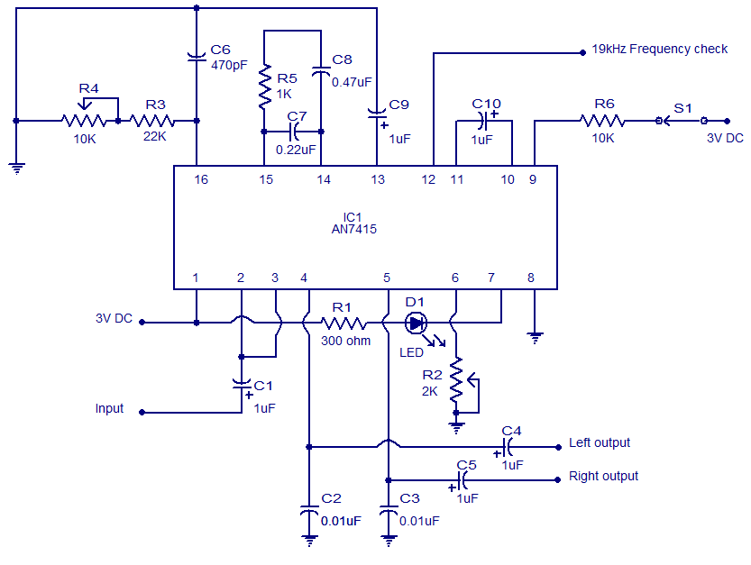
This weblog focuses on electronic circuit schematics, PCB design, DIY kits, and electronic project diagrams. The circuit presented is a stereo FM PLL demodulator based on the AN7415. C1 serves as the input coupling capacitor, blocking any DC voltage...
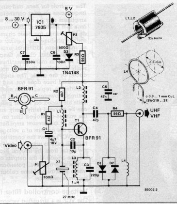
A simple oscillator generates a frequency in the VHF or UHF range. This oscillator is modulated with a video signal, and the resulting modulated carrier wave is transmitted to the TV set's aerial input through a cable. The final...
The RF modulator is a crucial component in televisions, VCRs, satellite receivers, format converters, home computers, and gaming consoles. This circuit is straightforward, stable, and easy to construct, allowing for seamless integration with various circuit boards. The schematic diagram...
The figure illustrates the 567 FM demodulator circuit. The FM signal is received at pin 3, while the demodulated output signal is available at pin 5. The central frequency of the FM signal that the circuit can demodulate is...
The advantages of synchronous reception of AM signals are well recognized, including high selectivity, linearity of detection, and a lower noise level at the output compared to other reception methods. The circuit diagram is illustrated in Figure 1. The...
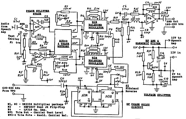
The circuit details are presented in Figure 3. The primary components of the system include a speech amplifier, an audio phase shift network with a balanced driver circuit (N1A, N2A), two balanced modulator stages (N1B & N2B), an RF...