
Smoke Alarm Circuit
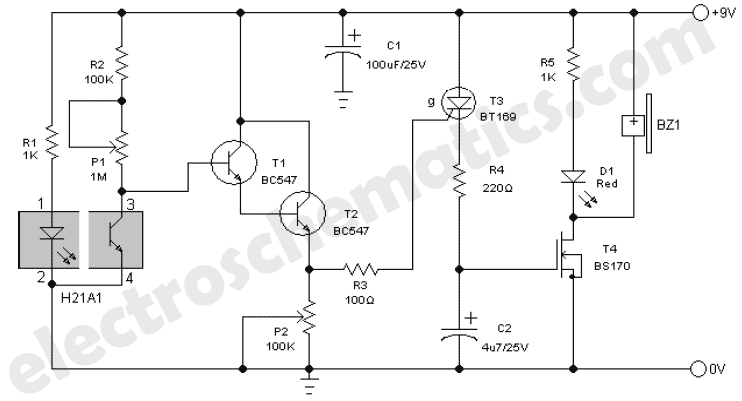
The updated smoke alarm circuit provides a robust solution for smoke detection by integrating an LM741 op-amp as a comparator to enhance performance and reliability. The design leverages a photo-interrupter, which effectively detects smoke by monitoring changes in current transfer ratios caused by obstructions in the light path. The use of a Darlington pair, specifically the H21B1, allows for lower power consumption while maintaining sensitivity. The transition to the Sharp GP series as a replacement for the discontinued H21A1/H21B1 series ensures continued availability of components for hobbyists and engineers alike.
The circuit's design prioritizes ease of understanding and implementation, making it suitable for educational purposes. The comparator configuration provides a clear threshold for smoke detection, with the op-amp output driving a MOSFET to activate an alarm system. The feedback mechanism involving capacitor C1 ensures that the alarm remains engaged for a brief period after smoke is cleared, preventing false negatives due to transient conditions.
The selection of resistors and capacitors is critical for fine-tuning the circuit to specific applications, allowing adjustments based on the characteristics of the photo-interrupter used. This flexibility is essential for achieving optimal performance across varying environmental conditions and component tolerances. Overall, the redesigned smoke alarm circuit represents a significant improvement over its predecessor, offering enhanced functionality, simplicity, and efficiency.The original smoke alarm circuit has some problems and has left some hobbyists and students disappointed. Rather than to attempt to solve its many problems, I have created an update that uses the venerable LM741 op amp.
It is simpler, more conventional, easier to understand and has much better battery life. The photo-interrupter is simply an opti cal coupler with the elements separated with a slot. Anything that enters this slot reduces the current transfer ratio (output current /input current). I used the H21B1 Darlington device since I did not have the H21A1 on hand. I am glad I did, because I learned that it is a better device, requiring far less LED current. Since the H21A1 /H21B1 series is no longer available from DigiKey, I selected a currently available, more inexpensive device ”the Sharp GP series ”see schematic(s) for details. Sharp appears to be the leader in this product. Although, I recommend the Darlington device, do not despair if you have the non-Darlington version. See the smoke alarm schematic for alternative devices /circuits. These were not tested, but I see no reason why they are not viable. I had my doubts as to the effectiveness of the technique, so I tested a photo-interrupter with smoke.
The oscillograph demonstrates what happens to the photo-transistor collector voltage when the gap is obscured with smoke from my soldering iron as it melted rosin core solder. Cool! It does work. The oscillograph also has a trace showing what happens when a transparent poly film is inserted into the gap.
It has a lower signature. I figured if it could see this effectively, it is an easier test, so the remaining testing is with film rather than smoke. Ambient light also affects the output voltage. In my case, it was only about ±0. 1V, but the sensor may need to be shielded from outside light sources if it is a problem. The old LM741 is a good choice, but I also found a low power substitute (TI TL061) that reduces battery current ”see schematic for details.
As it is, battery load is only 1. 1mA ”not bad! The LM741 is applied as a comparator /Schmitt trigger. The voltage on the inverting input is biased at 4. 2V (half of Vcc). The collector of the photo-transistor is adjusted via R2 for 4. 0V. Any reduction of the current transfer ratio causes the collector voltage to increase beyond 4. 2V. At this point, the output voltage of the op amp goes positive and turns on the MOSFET. The drain of the MOSFET drops to zero volts and C1 couples a positive feedback signal to the inverting input via R8. The R*C of R8 & C1 causes the LED & siren to stay on for at least 1sec after the smoke has cleared. C1 has to be either film or ceramic because the voltage polarity reverses. R1 must be selected to provide approx 4V at the collector of the photo-transistor with R2 centered. Its resistance is a function of photo-interrupter transfer ratio and may vary as much as 40:1. When this is selected, R2 will be within range of making operational adjustments. The question marks on the schematics are for this purpose ”actual resistance must be determined. In my smoke alarm circuit, one device required 10K while the other required 22K. 🔗 External reference
Related Circuits
The crystal radio derives its name from the galena crystal (lead sulfide) utilized for rectifying signals. A "cat's whisker" wire contact was adjusted on the crystal's surface until a diode junction was established. The 1N34A germanium diode serves as...
A discrete transistor current control circuit diagram. The discrete transistor current control circuit is designed to regulate the flow of current through a load by utilizing a transistor as the primary control element. This circuit typically consists of a few...
The circuit diagram of an IC Controlled Emergency Light with Charger, also known as a 12V to 220V AC inverter circuit, is presented here. This circuit features automatic activation of the light during mains failure and includes a battery...
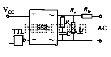
This document discusses the AC solid-state relay (AC-SSR) and presents its basic application circuit as illustrated in Figure (a). Additionally, it includes a TTL drive SSR circuit depicted in Figure (b), a CMOS driver circuit for the SSR shown...
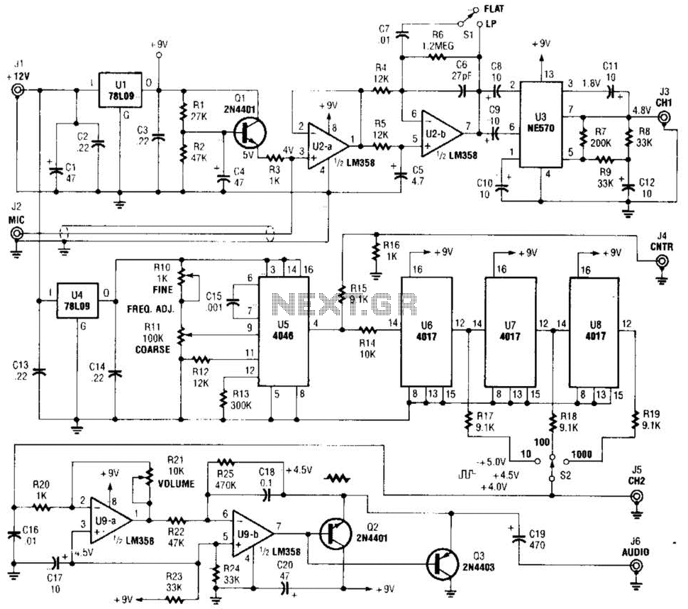
The precision audio frequency generator consists of several sub-circuits: an audio amplifier/filter circuit, an automatic level control, a variable voltage-controlled oscillator, a frequency divider circuit, an integrator, and an audio output amplifier. An electret microphone element is utilized to...

The TPS61200 specifications indicate that GND serves as the control/logic ground, while PGND is designated as the power ground. However, this distinction is not accurately represented in the symbols used in the diagram. There is also confusion regarding the...