
Siren alarm simulates star trek red alert
The described signal can be implemented as a waveform generator circuit that produces a repeating frequency sweep, mimicking the auditory alert commonly associated with the Star Trek red alert. The circuit can be constructed using a combination of operational amplifiers, resistors, capacitors, and possibly a microcontroller for precise timing and frequency control.
The waveform generator can utilize a triangle or sawtooth waveform to achieve the gradual rise in frequency. The operational amplifier can be configured in a non-inverting mode to amplify the output signal to the desired level. Capacitors and resistors can be selected to define the time constants for the frequency ramp-up and the pause duration. For instance, a resistor-capacitor (RC) network can be designed to achieve the 1.15 seconds rise time by calculating the time constant \( \tau = R \times C \).
To implement the 0.35 seconds pause, a flip-flop or timer circuit can be integrated to control the state of the output signal, ensuring that it remains at a low frequency during this interval. The output could then be fed into a speaker or buzzer to produce the audible alert.
For continuous operation, a microcontroller can be programmed to automate the timing cycles, allowing for precise control over the frequency transitions and pauses, thus ensuring the signal pattern repeats indefinitely. The microcontroller could also allow for adjustments in frequency ranges and durations through software, providing flexibility in the design.
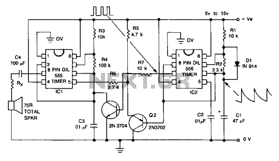
This circuit design can be used in various applications, including alarms, notifications, or any system requiring an attention-grabbing auditory signal. Proper attention to component selection and circuit layout will ensure reliable performance and sound quality.The signal starts at a low frequency, rises for about 1.15 seconds to a high frequency, ceases for about 0.35 seconds, then starts rising again from a low frequency, and so on ad infinitum. it sounds like the star trek red alert. 🔗 External reference
Related Circuits
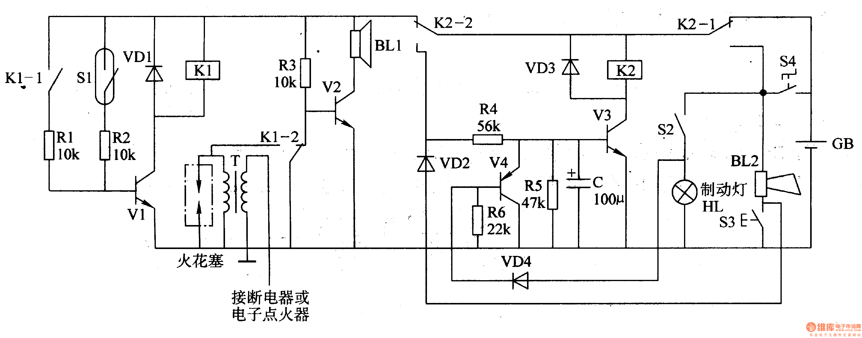
The circuit comprises a trigger circuit, an alarm control circuit, and a reset circuit for the alarm. The trigger circuit includes mercury switches (S1), a resistor, transistors (V1), and a relay (K1). The alarm control circuit is made up...
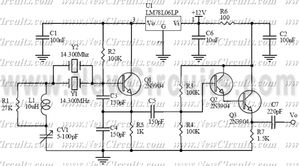
The circuit is a VXO with buffered output. It operates on the 20-meter amateur radio band with the output voltage about 0.2 Vp-p. The crystal frequency is pulled by tuning the variable capacitor CV1 about 36 kHz with only...
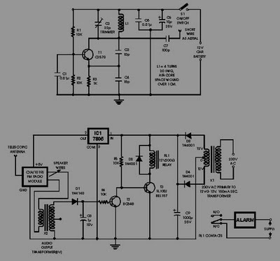
This circuit of an FM radio-controlled anti-theft alarm can be utilized with any vehicle that has a 6 to 12-volt DC supply system. The mini VHF FM transmitter is installed in the vehicle during the night when it is...
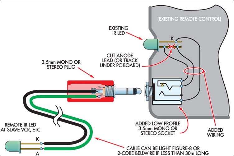
This ultra-simple remote control extender is ideal for use with a hidden video recorder. The recorder is a Panasonic NV-SD200 and is employed as part of a camera surveillance system. A PICAXE-08-based circuit detects events and controls the recorder....
With this circuit we can create a altered sound of siren. The oscillator IC1a-b is constituted by two gates NAND, oscillating in very low frequency. This oscillation drive the IC2, that is a electronic switch, which opens and closes...
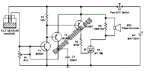
This design features a simple circuit for a tilt sensor alarm that can be constructed using readily available and inexpensive components. The circuit is based entirely on transistor technology. The homemade tilt sensor for this circuit utilizes a standard...