
Wailing Alarm Siren

IC2 operates as a low-frequency astable multivibrator, generating a square wave output with a defined cycle period, which is approximately 6 seconds in duration. The output waveform is characterized by a gradual ramp-up and ramp-down, which is critical for the modulation of the alarm signal. The ramp waveform produced at capacitor C1 is essential for the functioning of the emitter follower transistor Q1, which serves to buffer the signal and ensure that the modulation of the alarm generator IC1 is effective. The modulation process is achieved through the resistor R6, which influences the frequency response of IC1.
The alarm generator IC1 is designed to operate around a natural center frequency of 800 Hz, a frequency that is typically suitable for alarm applications. The cyclical nature of the output signal, which transitions from low to high frequency and back to low frequency, creates an alerting sound that can be easily perceived. The relationship between the loudspeaker LS and the resistor Rx is crucial for maintaining the desired output impedance of 75 ohms, ensuring that the alarm sound is produced at an appropriate volume level. The flexibility in the choice of Rx allows for adjustments based on the specific loudspeaker used, facilitating optimal performance across different speaker impedances.
Capacitors C2 and C3, specified as 0.01 µF (10 nF), play a role in filtering and stabilizing the circuit. The use of ceramic capacitors is recommended due to their reliability and effectiveness in high-frequency applications. The circuit's performance has been validated across various supply voltages, with 9 volts being the preferred choice for battery operation due to its efficiency and availability. It is important to avoid using 9V NiCad batteries, as their lower voltage output may hinder the circuit's operation, leading to inadequate performance of the alarm generator. Overall, this circuit design effectively combines astable multivibrator principles with frequency modulation techniques to create a functional alarm system.IC2 is wired as a low frequency astable with a cycle period of about 6 seconds. The slowly varying ramp waveform at C1 is fed to PNP emitter follower Q1, and is then used to frequency modulate alarm generator IC1 via R6. IC1 has a natural center frequency of about 800Hz. Circuit action is such that the alarm output signal starts at a low frequency, rises for 3 seconds to a
high frequency, then falls over 3 seconds to a low frequency again, and so on. * The Loudspeaker LS and the resistor marked "Rx" should be together 75 ohms. If you have a standard 8-ohm speaker then Rx is 67 ohms. The nearest value is 68 ohms. So for a 8 ohm loudspeaker Rx is 68 ohms. For a 4 ohm loudspeaker Rx is 71 ohms, for a 25 ohm loudspeaker Rx is 50 ohms, etc. The Rx value is not very critical. It is just there as some sort of volume control, experiment with it. C2 and C3 are 0. 01uF (10nF) and a simple ceramic type will do the job. I tested the circuit at 9, 12, and 15 volt. My personal choice is the 9 volt alkaline type for battery operation, or 12 volt for use with a small powersupply. The so-called 9V NiCad will not work properly. The actual voltage for this NiCad type is actually only 7. 5V (6 cells x 1. 2V = 7. 5V) 🔗 External reference
Related Circuits

Fire alarm circuit using an LDR (Light Dependent Resistor) as a flame sensor. It warns the user about fire accidents by detecting smoke produced during a fire. As smoke passes between an LED and an LDR, the amount of...
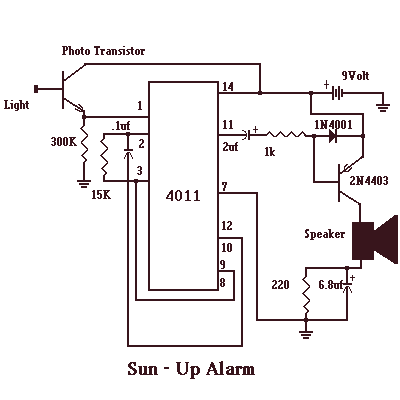
The Sun-Up Alarm can be used to provide an audible alarm for when the sun comes up or it can be used in a dark area and detect when a light comes on. It can also be used to...
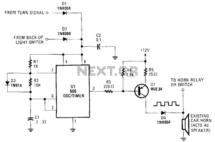
An auto horn operates as a speaker within a limited audio-frequency range. This circuit utilizes a 555 timer configured as an oscillator to drive an MJE34 transistor, which subsequently activates the horn. Normal horn operation is maintained through the...
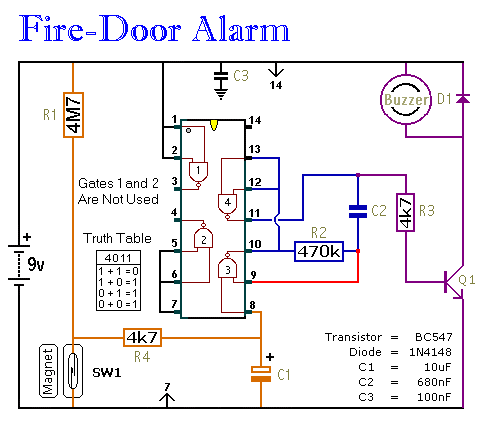
This circuit provides an alert when a door that should remain closed is left open. It is designed to be attached to a fire door, allowing normal passage. If the door remains open for more than 30 seconds, a...
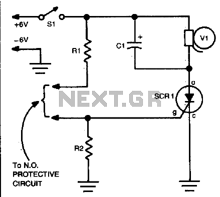
Closing the protective circuit (R1 to R2) applies positive voltage to the gate of SCR1 and activates the alarm. It can only be turned off with SI. The described circuit utilizes a Silicon Controlled Rectifier (SCR) as a key component...
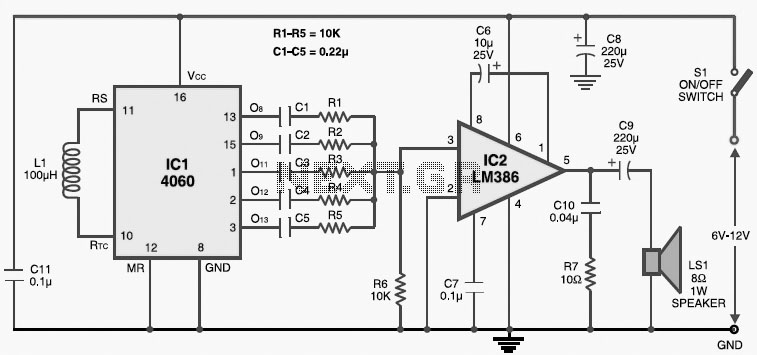
This multitone electronic siren is useful for burglar alarms, reverse horns, etc. It produces five different audio tones and is much more attention-grabbing than a single-tone siren. The circuit is built around the popular CMOS oscillator-divider IC 4060 and...