
Using C-52 EVB for simple robot experiments

The circuit utilizes the L293D H-Bridge driver to control the operation of DC motors, allowing for both direction and speed control. The inclusion of external diodes is critical for protecting the circuit against back EMF generated by the inductive loads. The PWM signal is generated through the enable pin, which modulates the power supplied to the motor, facilitating speed adjustments. The circuit design also incorporates inverters to ensure that the control signals are properly interpreted by the driver, thus enhancing operational reliability.
The integration of a PIC16C711 ADC expands the capabilities of the 89C52 microcontroller, enabling it to process analog signals, which is essential for applications like line tracking. The interfacing through a PISO protocol allows for efficient communication between the two microcontrollers, ensuring timely data transfer. The power supply circuit is designed to accommodate various battery types, ensuring versatility and ease of use. The careful selection of resistor values for the charging circuit is crucial for maintaining battery health and ensuring optimal performance.
Overall, this circuit design emphasizes the importance of proper component selection and circuit configuration to achieve reliable motor control and sensor interfacing, making it suitable for various robotics and automation applications.Basic circuit of using L293 formsan H-Bridge Driver is shown in Figure 1. As shown for such inductive loadas DC motor, external diodes for suppressing back EMF must be connected. The MiniBoard uses L293D instead, the L293D has internal diodes, howeverproviding a bit less driving capacity, i.
e. , 600mA @4. 5V-36V. From thetruth table, we see that dire ction of the motor can control by pin C andD. VINH enable/disable power to the motor, thus for speed regulation, wethen use this pin for PWM signaling. See details, L293. pdf data sheet. A circuit connecting C-52 P1 to L293 driver chip is shown in Figure2. As shown Enable pin 1 connected to P1. 0 is for PWM signaling. We useadditional inverter at pin7 and pin 15 to provide proper logic for easydirectional control. Please note that pin 4, 5, 12, 13 are tied to groundand if heat sinking needed, one method is to make a large area of PCB orsoldering it with a metal sheet, say.
Figure 2: Connecting C-52 EVB P1. 4-P1. 7 to L293. External diodes must be connected for L293(not shown in circuit diagram). My latest design put additional inverter forPWM signal at pin 1 and pin 9 to prevent full power delivering to DC motorswhen resetting the 89C52(i. e. , all bits of P1 is logic high). Check thelogic of PWM pins for another microcontrollers. Since there`s no ADC for 89C52 chip, each competitor may build theirown Line Tracking Sensor, some may use LM339 QUAD comparator with IR transmitterand receiver, some may use LDR as described in LineFollower Robot.
With an external comparator, it may not necessaryto have ADC, but with LDR, we need external ADC. " Having additional ADCfor 89C52 would be better", I thought. How can we provide ADC for 89C52with a cheap method I chose PIC16C711 with 4-channel ADC, and 7-pin inputport. Interfacing to 89C52 is done with simple PISO protocol by using RB0for SCLK and RA4 for SDA. The code for such purpose was written in C, hereis the source file, C52ADC. C and the HEXcode, C52ADC. HEX. After some initialization, the 711 chip wait for trigger read signal at pin RB0, i. e. , high-to-lowtransition, then it responses by sending 40-bit through RA4(SDA) with low-to-hightransition.
40-bit data stream begins with LSB of ADC0 to MSB of PORT B. Example of program fro testing ADC is ADC. C and the hex file is ADC. HEX. Figure 4 shows a simple power supply circuit. I have tested with KABO, it works fine. For those who have a big capacity rechargeable battery, the resistance value of R can be selected for approx. 10% output chargingcurrent. DC in can be higher if your battery voltage higher than 8. 4V, say. To ensure the output current is within the value calculated by R, measure DC current before. The maximum supply for LM317 is ~35V. Figure 4: Circuit Diagram of battery supply+12V Alkaline and +8. 4V NiMH with a constant current recharger circuit. For ~20mA, use R~60 Ohms. S1 is main switch for CPU and L293 circuits. Before writing PWM generation for testing above circuit, let study howto use Paul`s header. With a PAUL`s startup header at the beginning ofthe application C program, after successfully downloading the hex code, just press RESET, the 89C52 then will run the application instead of PAULMON2monitor program.
As long as the program remain in SRAM, running the programcan only be done with pressing RESET. To return to PAULMON2 prompt, turnthe board power off for a while, then back the power on again. This conceptof startup header allows us to use C-52 EVB as a dedicated controller besideas a learning board. Originally Paul has made with entirely in Assemblycode. However, I have adapted for Micro-C Compiler. I have put the headerfor startup code in the startup and runtime library for small memorymodel. The file C52ROBOT. ASM, will compileand link to the main( ) function with S=c52robot. asm when invoking commandcoordinator. Example of command line is; One method ofdelivering DC power to motors is to use P 🔗 External reference
Related Circuits
An LED flasher circuit can be constructed using a 555 integrated circuit (IC). The use of the 555 IC allows for greater flexibility in adjusting the flashing rate of the LED. This LED flasher circuit is similar to other...
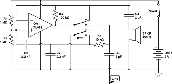
The circuit operates in receive mode, with the Push-To-Talk (PTT) switch enabling transmit mode. The speaker functions as both a microphone and a speaker. Most systems observed utilize a rocking armature transducer for the speaker. There is no base...
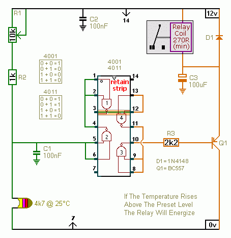
A CMOS 4001 or a CMOS 4011 can be utilized in this circuit, as both contain four two-input gates. The inputs of each gate are connected together, allowing them to function as simple inverters. This means that when both...
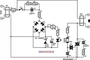
The following circuit illustrates an Automatic Light Dimmer Circuit Diagram utilizing a 1N4007 diode. Features include integration within a wall-mounted box. The Automatic Light Dimmer Circuit is designed to adjust the brightness of a light source automatically based on ambient...
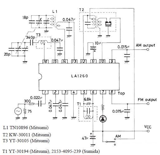
The FM IF MW radio receiver circuit schematic utilizes the LA1260 integrated circuit (IC) for AM and FM radio receiver electronic projects. The LA1260 incorporates numerous functions and features essential for radio receiver applications, including a high signal-to-noise ratio...
This is the basic interface I used as part of my Computerized Room project. This is the parallel interface only. The 8 bit input card can be found, along with the rest of the project, at Computerize Your Room/House....