
Warble-tone alarm

The circuit employs two integrated circuits (ICs) to create a distinctive warble-tone alarm, which mimics the characteristic sound of a British police siren. The first IC, designated as IC1, functions as an alarm generator. Its role is to produce a variable frequency output that simulates the siren's sound. The frequency modulation of IC1 is achieved through the second IC, IC2, which is configured as a 1 Hz astable multivibrator. This configuration allows IC2 to generate a square wave output at 1 Hz, which serves as the modulating signal for IC1.
Resistor R5 plays a crucial role in the circuit by connecting the output of IC2 to the input of IC1. This connection facilitates the modulation process, allowing the output frequency of IC1 to vary between 500 Hz and 440 Hz. The alternating output creates a distinctive sound pattern that is typical of a warble-tone alarm. Each complete cycle of the sound corresponds to the alternating frequencies, providing a clear and recognizable alarm signal.
In summary, the circuit effectively combines the functionalities of an alarm generator and a frequency modulator to produce a realistic simulation of a British police siren, utilizing simple components and a straightforward design approach. The alternating frequency output not only enhances the auditory effect but also ensures the alarm is attention-grabbing and effective in alerting individuals to potential hazards.The circuit generates a warble-tone alarm signal that simulates the sound of a British police siren. IC1 is wired as an alarm generator and IC2 is wired as a 1 Hz astable multivibrator. The output of IC2 is used to frequency modulate IC1 via R5. The action is such that the output frequency of IC1 alternates symmetrically between 500 Hz and 440 Hz, taking one sound to complete each alternating cycle. 🔗 External reference
Related Circuits

This circuit emits a beep and/or illuminates a LED when someone touches the door-handle from the outside. The alarm will sound until the circuit will be switched-off. The entire circuit is enclosed in a small plastic or wooden box...

This circuit is capable of generating up to 1 W of audio power to drive a speaker or horn. When the CDS cell is exposed to light, its resistance decreases, activating NOR gate (a). This activation causes gates (a)...

A low-frequency oscillator (Q1) modulates a high-frequency oscillator (Q2) along with its associated timing capacitor. The output frequency varies continuously. The circuit comprises two primary components: the low-frequency oscillator (Q1) and the high-frequency oscillator (Q2). The low-frequency oscillator is responsible...

This circuit utilizes invisible infrared light to detect the movement of individuals passing through a doorway. A short beep is produced when the infrared beam is interrupted. The circuit operates by employing an infrared transmitter and a receiver. The transmitter...
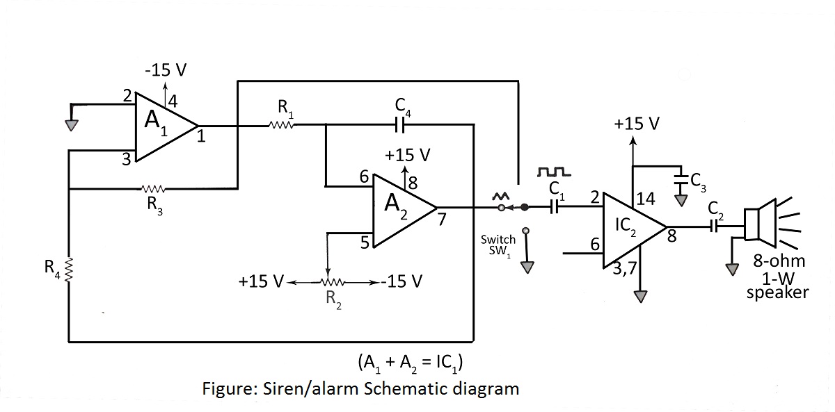
A simple siren or alarm circuit utilizing the MC1458 dual op-amp and the audio power amplifier LM380 is presented. The circuit diagram includes various configurations for sirens, doorbells, and alarm systems, along with a comprehensive parts list. The circuit operates...

This is a complete alarm system with five independent zones suitable for a small office or home environment. It utilizes three CM integrated circuits and features a timed entry/exit zone, four immediate zones, and a panic button. There are...