
Warning light
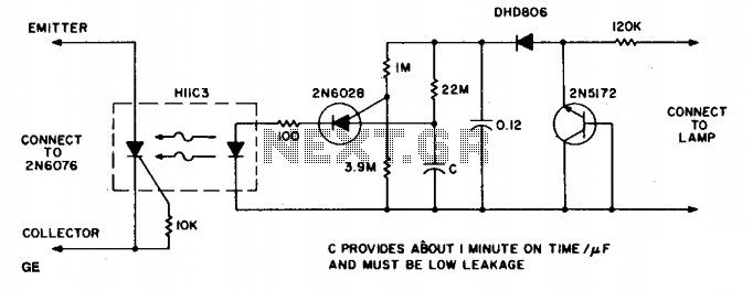
This circuit employs a photodarlington sensor, which is highly sensitive to light levels, making it ideal for detecting darkness. When ambient light levels drop below a predetermined threshold, the photodarlington sensor activates, triggering the Darlington amplifier. The Darlington amplifier, known for its high current gain, allows for a minimal input current to control a larger output current, effectively powering the illumination source, such as an LED or incandescent bulb.
The circuit includes three resistors that serve multiple purposes: one resistor is typically used to set the biasing conditions for the photodarlington sensor, ensuring it operates within its optimal range. Another resistor is often placed in the feedback loop of the Darlington amplifier to stabilize the gain and prevent oscillations. The third resistor may be employed to limit the current flowing through the illumination source, thereby protecting it from potential damage due to excessive current.
The D40K component is notable for its low saturation voltage, which means that when the circuit is activated, the voltage drop across the Darlington pair is minimized. This results in a slightly reduced operating voltage for the lamp, which not only lowers the illumination level but also contributes to an extended lifespan for the bulb. The overall design emphasizes efficiency and longevity, making it suitable for applications where automatic illumination is desired, such as in outdoor lighting systems or automatic night lights.The circuit provides illumination when darkness comes. By using the gain available in darlington transistors, this circuit is simplified to use just a photodarlington sensor, a darlington amplifier, and three resistors. The illumination level will be slightly lower than normal, and longer bulb life can be expected, since the D40K saturation voltage lowers the lamp operating voltage slightly. 🔗 External reference
Related Circuits
This handy little circuit can tell the difference between darkness and light, making it very useful for switching on and off signs, porch lights or other things when it gets dark or light. More: R1 Adjusts sensitivity The circuit described...
This simple and inexpensive circuit is not limited to Christmas use. It consists of two resistors, a small-signal transistor such as a BC547, and a flashing LED. The circuit operates by utilizing a small-signal transistor, which acts as a switch...
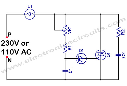
Filament Light Dimmer Circuit. This simple triac dimmer can be used to control incandescent filament lamps up to 200W. The circuit operates on standard AC voltage. The filament light dimmer circuit utilizes a TRIAC to control the power delivered to...
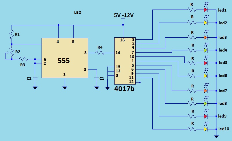
This is a LED sequencer circuit where 10 LEDs light up and turn off sequentially, creating a chasing effect. This simple circuit is suitable for designing lighting decorations on Christmas trees. It can also be used for lighting animations...

The circuit consists of an oscillator, a counter, and an Iseki circuit divided into three parts. The oscillator is based on the NE555 timer and several external RC components, generating a pulse signal for the counter. The instantaneous power...

Up to six lights can be sequentially flashed using this circuit. LED1 through LED6 can be replaced by optocouplers (MOC3010, etc.) to control 120-Vac loads via triacs. Ul generates pulses that clock the shift register mode of the six...