
12V Fan controller with PIC18F25K20
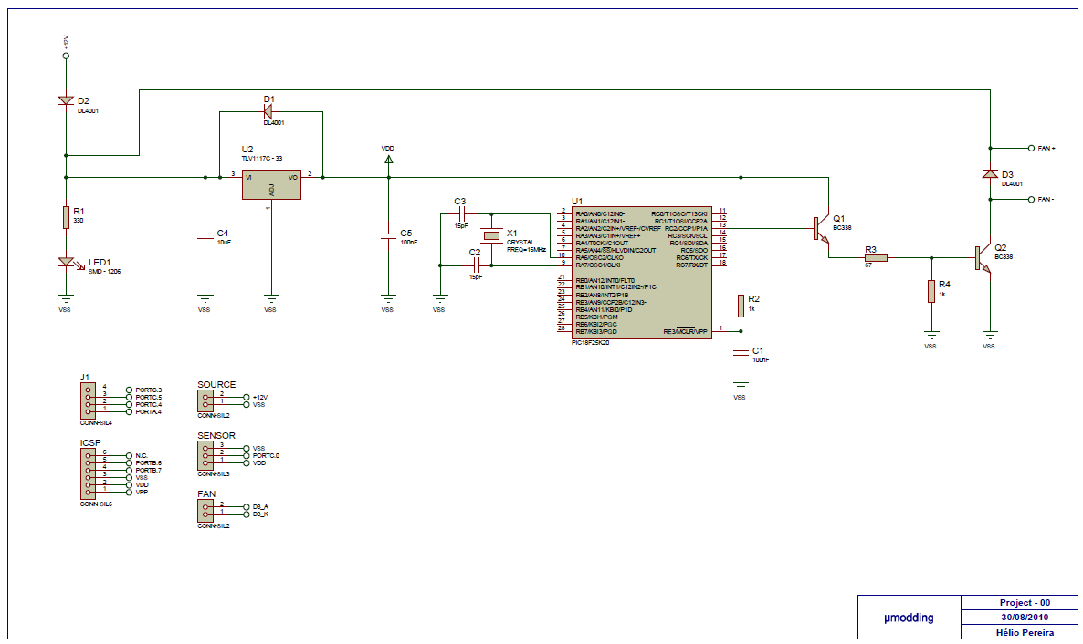
The circuit utilizes a PIC18F25K20 microcontroller, which serves as the central processing unit for controlling the fan's operation based on temperature readings. The DS18B20 temperature sensor provides accurate temperature measurements, which are processed by the microcontroller to determine the appropriate fan speed. The PWM signal generated on PORTC.2 allows for precise control of the fan speed by varying the duty cycle.
The BC338 transistor is employed as a switching device to amplify the PWM signal from the microcontroller. Given that the microcontroller output is limited to 3.6V, a secondary transistor configuration is necessary to ensure that the base current is sufficient to drive the BC338 into saturation. This configuration allows the fan to operate effectively at higher voltages, ranging from 5V to +/-12V, accommodating various fan specifications.
The design incorporates protective measures, including diode D3, which safeguards the circuit from back EMF generated by the fan's inductive load. This diode is critical in preventing damage to the transistors during the switching process. The overall design allows for the control of multiple fans, provided that the total current does not exceed the rated capacity of the BC338, ensuring reliable and efficient operation in various environmental conditions.This project it´s based on a PIC18F25K20, with the purpose of control a FAN with PWM (Pulse with Modulation). It offers a variable speed control, low acoustic noise, reliability, long lifetime, low power consumption, protection features.
The MCU get the temperature from the sensor (D18B20), and after will do a conversion Celsius degrees and then it´s generated a PWM on PORTC.2 with 6 different levels. After the signal goes to Q1 (BC338) in order to control the duty cycle in the fan. I had to use two transistors to have an Ic on Q2 to be enough to activate the fan. Because the MCU only generate a maxim of 3.6V on which output, and 15% of 3.6V is 0.5V to polarize Q1 we need 0.7V. You will be able to control the FAN between 5V and +/-12V.The BC338 have a current load of 800mA that is value of a fan can have, you can use two or more fans as long the current load isn´t more than 800mA.
The output of MCU connect to the Q1 and Q2 it works like a switch, the D3 it´s for protection from the magnetic field in the inductors from the FAN, without the D3 when you turn off the system the current will be discharge to the Q2 and could damage it. 🔗 External reference
Related Circuits
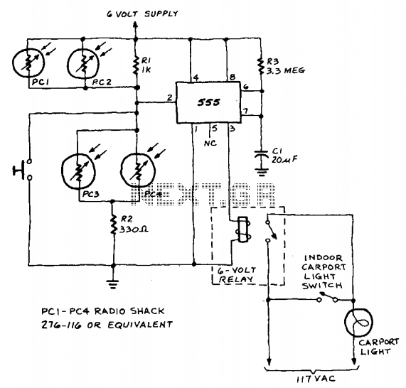
A 555 timer integrated circuit (IC) functions in one-shot mode, triggered by light exposure to photoresistors. These photoresistors typically exhibit a resistance in the range of several megohms, which decreases to several hundred ohms under light conditions, allowing current...
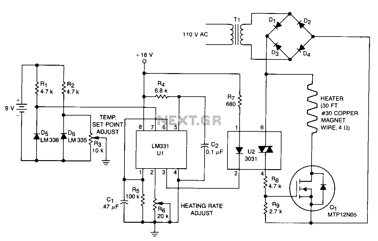
This temperature controller functions as a pulse snatching device, enabling it to operate at its own speed and activate at the zero crossing of the line frequency. The zero crossing activation minimizes the generation of line noise transients. A...
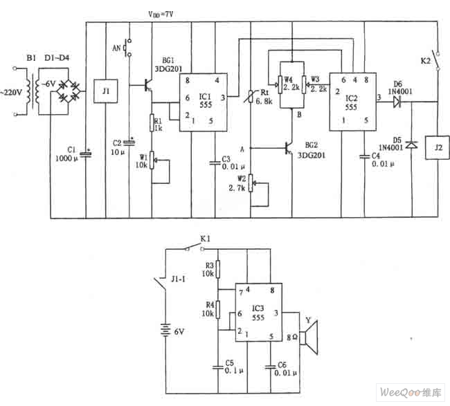
The figure illustrates the automatic watering control circuit for bean sprouts. The controller includes a step-down rectifier circuit, a power outage detection component (IC3), a timing control circuit (IC1), and a temperature control circuit (IC2). The step-down rectifier circuit...
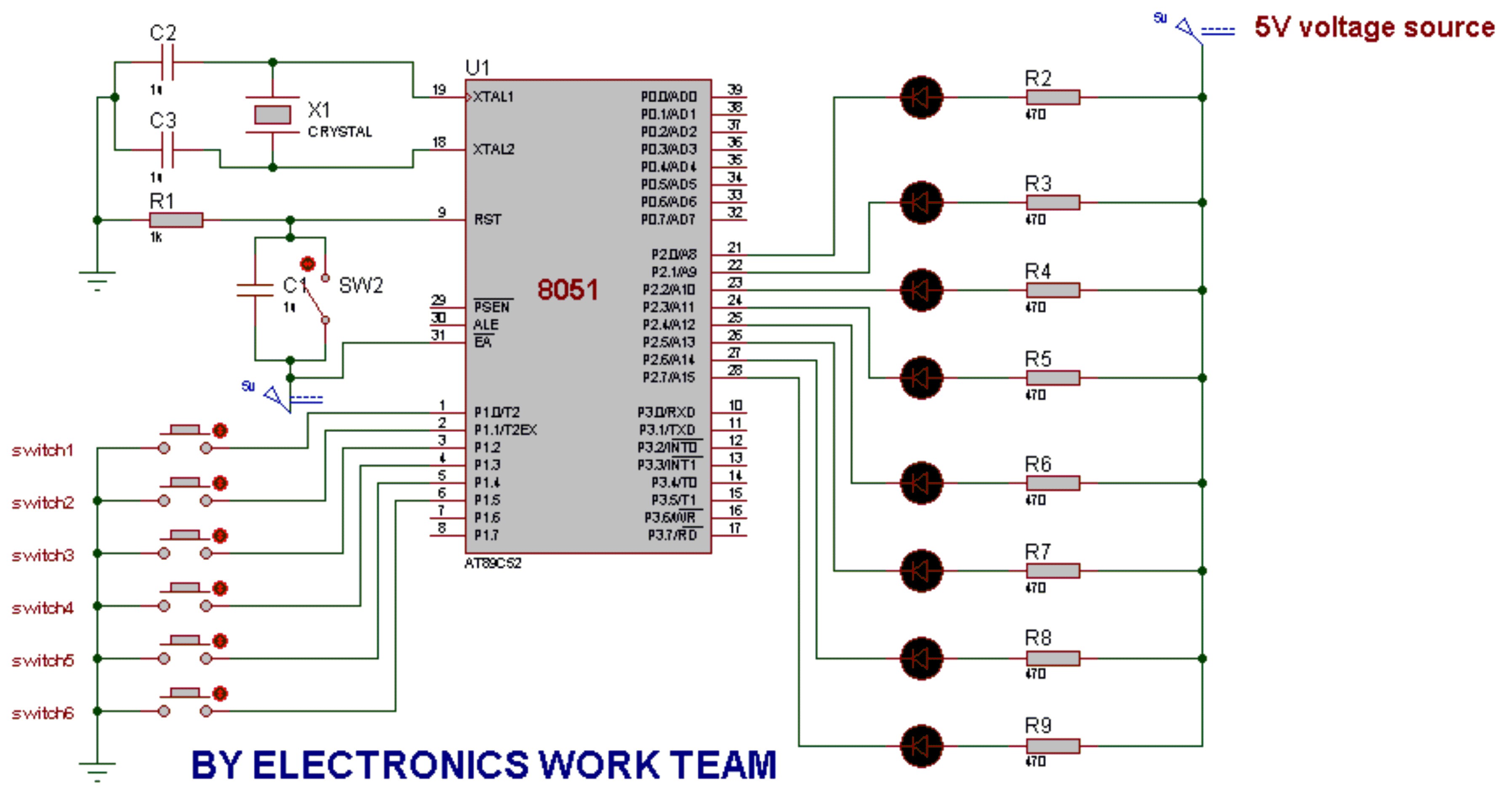
This post discusses the fundamental operation of the 8051 microcontroller using LEDs. The LEDs are connected to the P2 port, while six switches are connected to the P1 port of the 8051. By pressing various switches, the LEDs will...
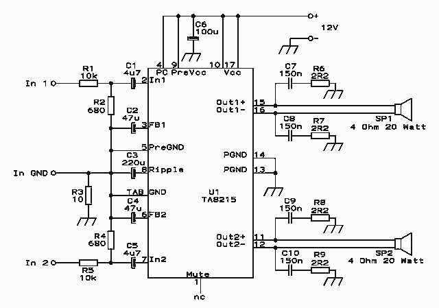
While I would have liked a 4 channel chip with about 20 Watt per channel, the local parts store didn't have any yet, so I opted for two TA8215AH stereo chips, selected by their low price in this particular...

This circuit is similar to the one found in the Single Buss 1V/Octave Keyboard Controller. Refer to the circuit description there for more details. This board includes additional resistors used in the keyboard voltage divider. In a typical keyboard,...
Warning: include(partials/cookie-banner.php): Failed to open stream: Permission denied in /var/www/html/nextgr/view-circuit.php on line 713
Warning: include(): Failed opening 'partials/cookie-banner.php' for inclusion (include_path='.:/usr/share/php') in /var/www/html/nextgr/view-circuit.php on line 713