
7-segment display with encoder

We suggest reading the counter project pages for a detailed description of the 4511 and 7-segment displays. All of the display connections are handled by the 4511 itself. The display, a common-cathode part, has been selected because it fits nicely on a breadboard, but it can be replaced with another brand or model provided it is a common-cathode type. Different parts can have different pinouts, therefore requiring different board wiring to suit the new layout. To pinpoint all of the pins, power the display with a 5V source connected in series with a 390-ohm resistor (for limiting the current). Power different pin pairs until the whole pin/segment pattern is discovered.
The incremental-type (also known as quadrature-type) encoder connects directly to a couple of input pins (IN1 and IN2). An encoder can be thought of in terms of a pair of switches (A and B encoder pins) with one of their pins connected together (COM pin). This common pin is connected to GND; therefore, from the Nutchip's perspective, the A and B switches act like any other pair of common switches. The Nutchip reads a "1" on the input when the switch is open and a "0" when the switch is closed. No other parts are required, as Nutchips include an internal pull-up resistor which makes the input positive (a logic "1") whenever the pin is not connected to any other potential.
Turning the encoder knob causes the encoder switches to close/open according to a well-known pattern, changing the logic state of IN1 and IN2 pins on the Nutchip. Whenever the knob is in a rest position, both switches A and B are open. When the encoder is moved from one position to another, the switches close according to the following sequence: A, A+B, B, then both open on the next detent when moving clockwise. In the case of counterclockwise operation, the sequence reverses to B, B+A, A, and both open again. It is important to note that different encoders other than the one from ALPS can have a slightly different detent configuration, which may require two "clicks" to increment the count by one.
Due to the relatively high number of connections involved, this project requires extra care to avoid mistakes. The prototype is assembled on a solderless breadboard, with sufficient wire jumpers to ensure all connections are secure. It is advisable to check all connections against a reference photo, as some of the jumpers may cross and overlap each other. The encoder used in this design is manufactured by Alps and provides three pins spaced 5.08 mm apart. While it could theoretically fit the breadboard spacing, an adapter was constructed from an old dual-in-line IC socket and some insulated copper wire. The socket was halved, cutting out five pins, and soldering a length of wire to each remaining pin. This adapter facilitates proper connection, with color-coded wires indicating pin A (green), pin B (white), and the common pin (black).This design explains how to use an encoder to set the number shown by a 7-segment display. Turn the knob clockwise to increment the number, turn it counterclockwise to set it back. Encoders are the most practical (and handy) way to set a large number of digital devices. Think of an alarm clock, would'nt be easier to set the alarm time simply turning a knob, in place of frantically pressing a couple of buttons? By the way, grandma alarm clock works exactly in that way. The circuit counts four main parts (Nutchip, encoder, display driver and display), nonetheless should not be difficult to understand.
Its a matter of connecting two Nutchip inputs to the two encoder pins, and all four Nutchip outputs to a 4511 7-segment display driver. We suggest you to read the counter project pages for a detailed description of the 4511 and 7-segment displays. Here we note how all of the display connections are handled by the 4511 itself. The display, a common-cathode part, has been selected because it fits nicely a breadboard, but you can replace it with another brand or model provided it is a common-cathode type.
Also, different parts can have different pinouts, therefore require a different board wiring to suit the new layout. To pinpoint all of the pins, try to power the display with a 5V source connected in series with a 390 ohm resistor (for limiting the current).
Try powering different pin pairs until the whole pin/segment pattern is discovered. A good puzzling game for a rainy day, if nothing else... The incremental-type (also known as quadrature-type ) encoder connects directly to a couple of input pins (IN1 and IN2). We can think of an encoder in terms of a pair of switches (namely A and B encoder pins) with one of their pins connected together (COM pin).
We connected this common pin to GND; therefore, from Nutchip's perpective, the A and B switches acts like any other pair of common-or-garden switches. The Nutchip reads an "1" on the input when the switch is open, and a "0" when the switch is closed. No other parts are required, as Nutchips include an internal pullup resistor which makes the input positive (a logic "1") whenever the pin is not connected to any other potential.
Turning the encoder knob causes the encoder switches to close/open according to a well-known pattern, changing the logic state of IN1 and IN2 pins on the Nutchip. Whenever the knob is in a rest position, both the switches A and B are open. The magic happens when moving the encoder from one position to another (positions are determined by the number of detents on the shaft).
If the shaft moves clockwise, the switches close according to the following sequence: A, A+B, B, then both open on next detent. In case of counterclockwise operation, the sequence reverses to B, B+A, A, and both open again. Note that different encoders other than the one from ALPS we used (see photo) can have a slightly twice a number of detents, whith the above sequence stopping also in places with both the switches closed.
In this case, the circuit works as well, but it is necessary to step two "clicks" to increment the count by one. Because of the relatively high number of connections involved, this project requires extra care in order to avoid mistakes.
We assembled our prototype on a solderless breadboard. Ensure you have enough wire jumpers; also, check all connections against the photo as some of the jumpers cross and overlap each other. The encoder used in this design is manufactured by Alps and provides 3 pins spaced apart 5.08 mm each.
It could theoretically fit the breadboard spacing, nonetheless we preferred to build an adapter from an old dual-in-line IC socket and some spare insulated copper wire. We halved the 2.54 mm IC socket, cutting out 5 pins, and soldering a length of wire each other pin. This kind of adapter worked well, see photo below; the green wire is pin A, the white one is pin B, and the common pin refers to black wire.
🔗 External reference
Related Circuits
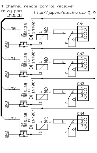
This is a general-purpose remote control project utilizing programmable PIC microcontrollers. Schematics are provided for using infrared (IR) or radio frequency (RF) media. If microcontroller programming is unfamiliar, fixed encoder and decoder integrated circuits can be employed instead. Well-known...

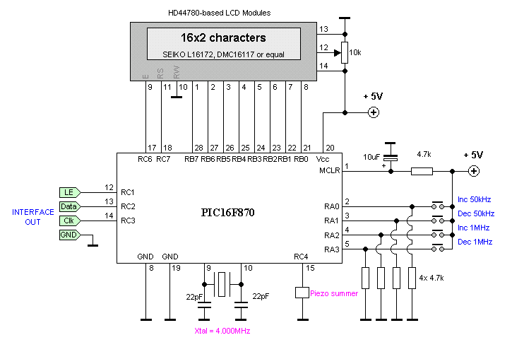
The programmed Signetics 8223 256-bit PROM is utilized as an alphanumeric display featuring five 7-segment digits, which are interconnected to simulate abbreviations for units of measurement such as seconds, milliseconds, microseconds, hertz, kilohertz, and megahertz, represented as SEC, SEC-3,...
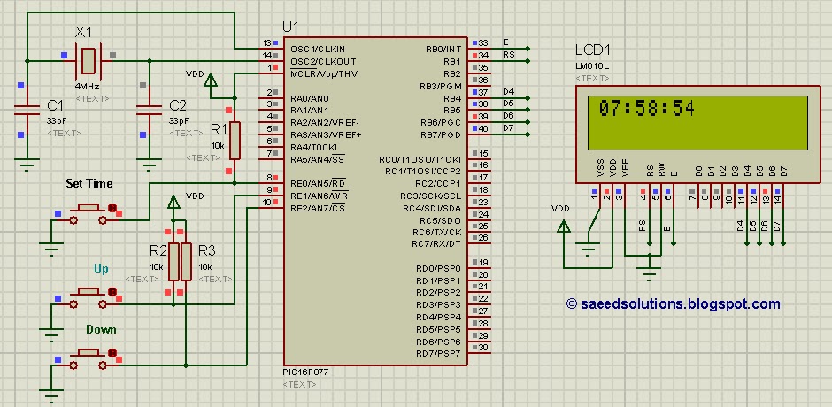
This tutorial on the PIC16F877 microcontroller addresses the question, "How to implement a controllable digital clock using the PIC16F877?" It utilizes the PIC16 simulator for demonstration purposes. The implementation of a controllable digital clock using the PIC16F877 microcontroller involves several...
Each step will result in a self-functional unit. By the end of this process, it will be possible to link the steps together into a powerful FM transmitter. This section will explain the main controlling unit for the FM...
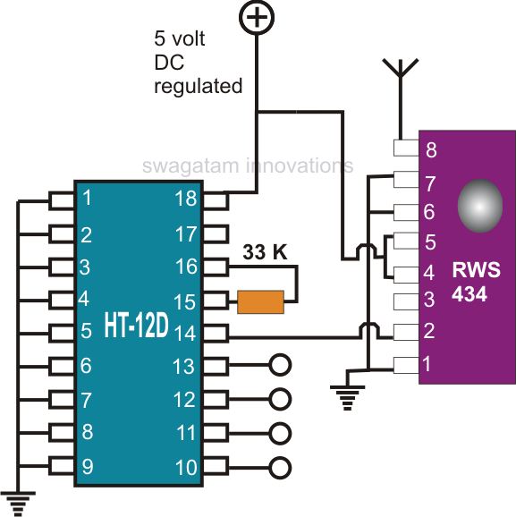
Creating a universal remote control system has become quite straightforward. One can acquire the necessary chips, assemble them, and the high-tech remote control device will be operational. This document discusses specific remote control chips designed for this purpose. The...

Light-emitting diodes (LEDs) are advantageous due to their compact size, low current consumption, and vibrant colors. This circuit features a running message display where the letters formed by an LED arrangement illuminate progressively. Once all letters of the message...