
Fast Composite Amplifier Circuit
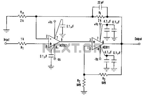
The device can be modified to provide an overall gain of 5 by adjusting both the R/Rm ratio and the R2/R1 ratio to 4:1. This adjustment increases the gains of the AD811 and the total circuit while keeping the AD797 at unity gain. Changing only the R/Rm ratio may lead to circuit instability, whereas altering only the R2/R1 ratio will allow the AD797 to operate at gain, resulting in a reduced overall bandwidth. The resistor Ri should be set to the parallel combination of Rm and Rf.
The described circuit utilizes a combination of high-performance operational amplifiers to achieve superior signal integrity and low distortion. The AD797, known for its ultra-low noise characteristics, is complemented by the high-speed capabilities of the AD811, creating a composite amplifier that excels in applications requiring high precision, such as analog-to-digital conversion and automated test equipment. The design emphasizes maintaining low total harmonic distortion, making it suitable for high-fidelity audio applications and sensitive measurement systems.
The operational amplifiers are configured to optimize their strengths; the AD811's higher gain compensates for the AD797's slower response, enabling efficient signal processing without sacrificing performance. The ability to modify the gain through resistor ratios provides flexibility in circuit design, allowing for adaptation to specific application requirements while ensuring stability and performance.
In practical implementation, careful selection of resistor values is crucial. The Ri value, determined by the parallel combination of Rm and Rf, plays a significant role in maintaining the desired bandwidth and stability of the system. The circuit's performance can be further enhanced by utilizing precision resistors and capacitors to minimize additional noise and distortion introduced by the components themselves. Overall, this composite amplifier circuit stands out as a robust solution for high-performance electronic applications. An ultra-low-noise, low-distortion op ampthe AD797is combined with the ADS 11 op amp, which offers a high bandwidth and a 100-mA output drive capability. The composite-amplifier circuit serves quite well when driving high resolution ADC`s and ATE systems.
The fast AD811 operates at twice the gain of the AD797 so that the slower amplifier need only slew one-half of the total output swing. Using the component values shown, the circuit is capable of better than -90 dB THD with a 5-V, 500-kHz output signal.
If a 100-kHz sine-wave input is used, the circuit will drive a 600- load to a level of 7 V rms with less than -109 dB THD, as well as a 10-kQ load at less than -117 dB THD. The device can be modified to supply ari overall gain of 5 by changing both the R/R-m ratio and R^R2 ratio to 4:1. This raises the gains of AD811 and the total circuit while maintaining the AD797 at unity gain. If only the R/Rm ratio is changed, the circuit might become unstable. In contrast, if only the RJR2 ratio is varied, the AD797 will then operate at gain. Subsequently, the circuit will have a lower overall bandwidth. Ri should be equal to the parallel combination of Rm and Rf. 🔗 External reference
Related Circuits
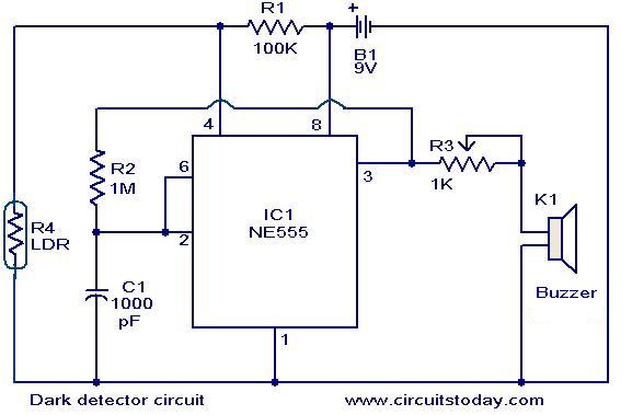
The dark detector circuit illustrated here is designed to generate an audible alarm when the ambient light in a room is turned OFF. The circuit is constructed around the timer IC NE555. A general-purpose light-dependent resistor (LDR) is utilized...

The circuit is designed to fit snugly, eliminating the need for adhesive. It is recommended to test the fit multiple times, making incremental adjustments until a snug but movable fit is achieved. The entire circuit should be placed inside...
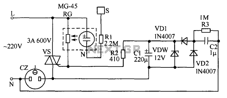
The circuit operates by detecting a finger touch on a metal sheet (S), which activates a neon tube light (N). The combination of the neon tube and a photoresistor (RG) acts as an optocoupler, reducing the resistance of RG....
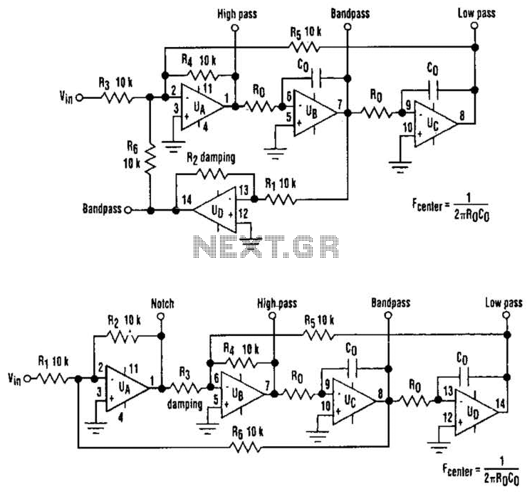
The classic state-variable (two-integrator) filter is well-known for its insensitivity to device parameter tolerances and its capability to provide three simultaneous separate outputs: high pass, bandpass, and low pass. These advantages often outweigh the requirement of a quad operational...
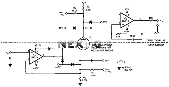
This amplifier can transfer DC to 5 MHz signals across a potential difference of 25,000 V. It can be utilized in CRT displays and high-voltage applications. It is important to note that the tube must be shielded due to...
This document presents a collection of engaging and challenging electronic circuits that can be built for enjoyment. The author has a long-standing passion for electronics, having studied the subject since middle school and developed numerous circuits over the years....