
Power-On Time Delay Relay circuit
The described circuit employs a 2N3904 transistor configured in reverse bias to exploit the breakdown characteristics of its emitter-base junction, effectively acting as a zener diode. This configuration allows for a stable voltage reference of approximately 8 volts, which is crucial for controlling the turn-on characteristics of the subsequent Darlington pair. The Darlington transistor configuration, known for its high current gain, is typically used to drive larger loads such as relays.
Upon power-up, the circuit initiates a delay before the relay is activated. This delay is achieved by charging a capacitor connected to the base of the Darlington pair. Initially, when power is applied, the capacitor remains uncharged, preventing the Darlington pair from turning on. As the capacitor charges through a resistor, the voltage across it gradually increases. Once the voltage exceeds the threshold required to turn on the Darlington pair, the relay is activated, allowing current to flow through the load.
The choice of components, such as the 2N3904 transistor and the specific values of the resistor and capacitor, will determine the time delay duration. Adjusting these values can tailor the circuit for various applications, such as providing a delay in activating a device after power is applied, ensuring that transient conditions are stabilized before the relay engages.
In summary, this power-on time delay relay circuit is an effective solution for applications requiring a controlled delay in relay activation, leveraging the unique properties of bipolar transistors in conjunction with passive components.Here`s a power-on time delay relay circuit that takes advantage of the emitter/base breakdown voltage of an ordinary bi-polar transistor. The reverse connected emitter/base junction of a 2N3904 transistor is used as an 8 volt zener diode which creates a higher turn-on voltage for the Darlington connected transistor pair..
🔗 External reference
Related Circuits
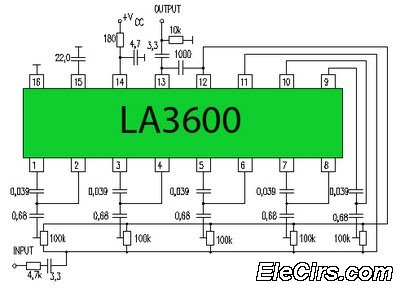
Circuit LA3600 5 Band Equalizer Circuit Schematics. One type of tone control in audio electronics is the graphic equalizer. Graphic equalizers can be categorized into two types: bar and other configurations. The LA3600 circuit is a 5-band graphic equalizer designed...
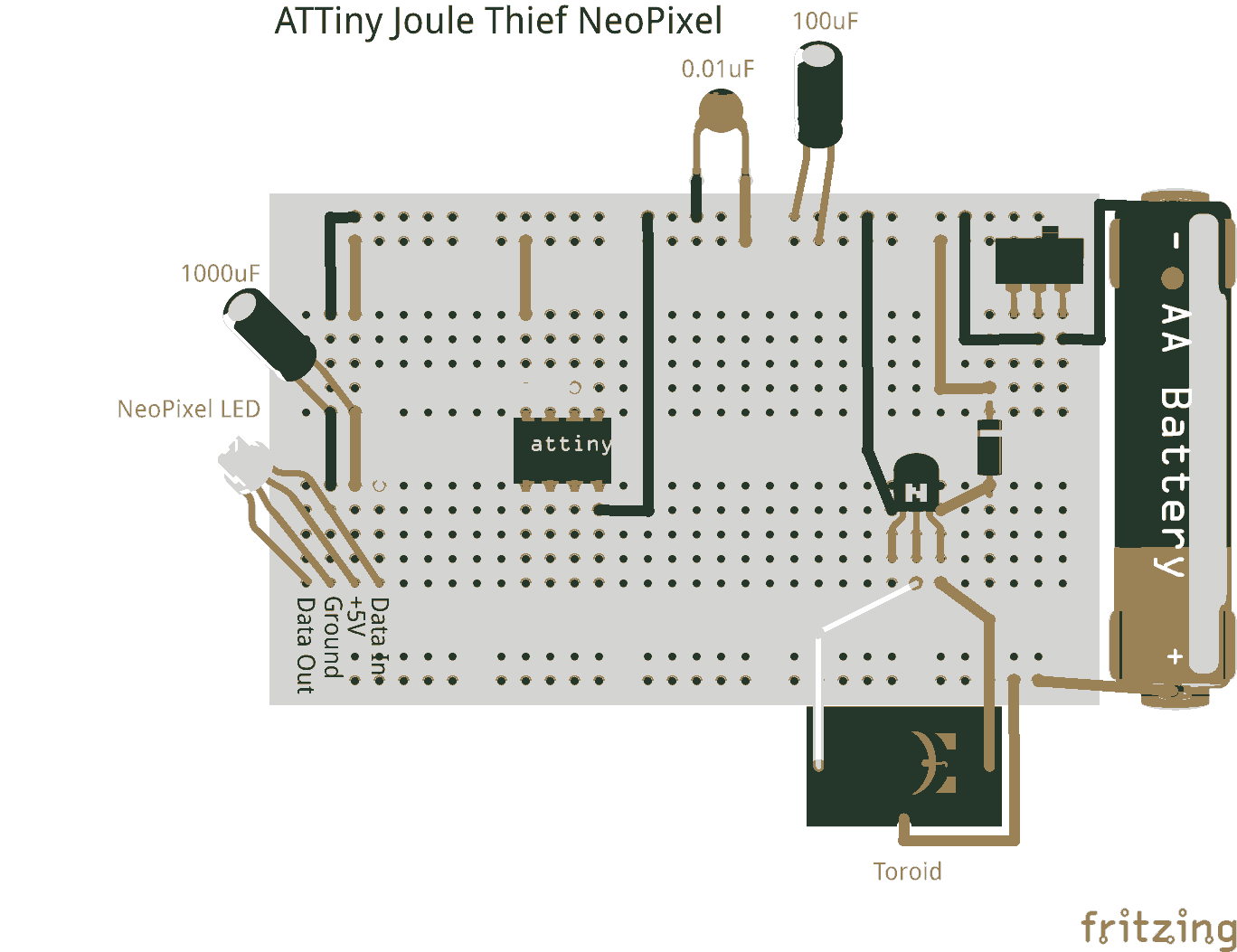
Joule thieves are not limited to illuminating standard LEDs. They can be utilized with an ATtiny microcontroller to power NeoPixel LEDs. Joule thieves are simple and efficient circuits designed to extract and boost low voltage energy from sources such as...
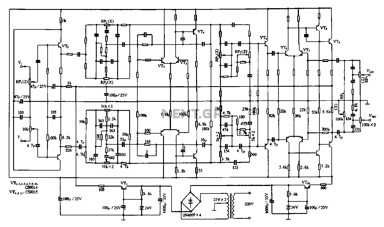
Figure 4-11 illustrates a feedback attenuator that comprises a transistor-based tone control circuit. This circuit features a conventional high and bass control system, along with balance control, volume control, loudness adjustment, and subwoofer control, as well as field sense...
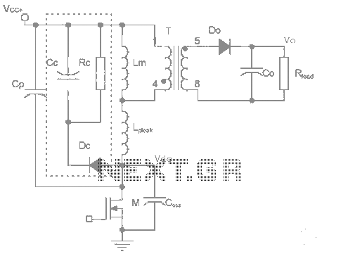
The work process analysis circuit diagram illustrates the use of a flyback converter transformer model. The flyback transformer primarily consists of ideal transformer magnetizing inductance and leakage inductance components. The flyback converter circuit exhibits high-frequency resonance at both ends...
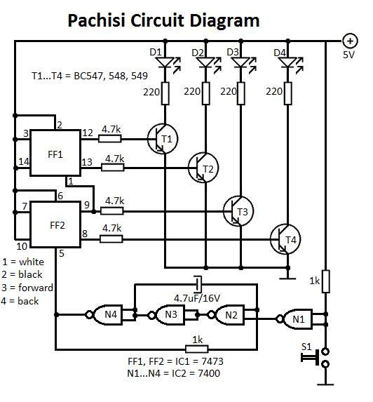
The Pachisi game is designed for two players. Each player has one figurine, which is initially placed on positions indicated by arrows on the game board. The Pachisi game, often referred to as the "Royal Game of India," is...
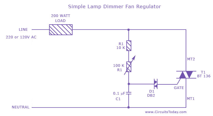
A fan regulator circuit that can also function as a simple lamp dimmer circuit. This fan speed regulator or light dimmer operates based on power control using a triac. The fan regulator circuit is designed to control the speed of...