
water liquid level sensor relay switch

The water level sensor relay switch circuit is an efficient solution for managing liquid levels in various applications, such as aquariums, water tanks, and swimming pools. The design primarily consists of a water level sensing mechanism, an NPN transistor (2N2222), a relay, and the necessary resistors for biasing the transistor.
The two probes, typically made of conductive material, are positioned at specific heights within the tank or container. When the water level rises to the height of the probes, the water acts as a conductive medium, completing the circuit between the probes. This causes a small current to flow, which is sufficient to bias the base of the 2N2222 transistor, turning it on.
Once the transistor is turned on, it allows a larger current to flow from the collector to the emitter, activating the relay. The relay, in turn, can control a higher voltage circuit, such as a water pump, enabling it to switch off automatically when the water level reaches the desired point. The relay used in this circuit can be rated for either six volts or twelve volts, depending on the power supply available for the application.
To ensure the reliability of the circuit, it is important to include appropriate resistors to limit the current flowing into the base of the transistor, preventing damage and ensuring proper operation. Additionally, a flyback diode should be connected across the relay coil to protect the transistor from voltage spikes generated when the relay is deactivated.
This circuit exemplifies a practical application of basic electronic components in automating water level control, contributing to energy efficiency and enhancing safety in environments where water levels need to be monitored and controlled.Here is a schematic of a simple water or liquid level sensor relay switch circuit, which can be used to switch on or off electronic appliances at the desired level of water. The circuit is ideal for automatically switch off the water pump when your water tank, pool or aquarium is filled.
The circuit is very easy to build and contains only few part s. The NPN transistor 2N2222 is working as a switch, when the two probes shown in the circuit will detect water the transistor become switch on and activates the six volts relay For operating the circuit with 12 volts use a 12 volt relay. 🔗 External reference
Related Circuits

Development board featuring high-power relays, opto-coupled inputs, a power supply circuit, a crystal oscillator circuit, and an RS232 port, along with ICSP and JTAG ports. The JTAG connector utilizes a 5x2 pin configuration for in-circuit programming. This development board is designed...
If you are an effects builder or repairer, you know that it is a good idea to protect the circuitry in the effect from the consequences of a reversed battery. While many older effects can withstand a momentary reversal,...

A simple 5-volt switching power supply electronic circuit project can be designed using the FAN302HL, a highly integrated PWM controller integrated circuit. This IC provides several features that enhance the performance of general flyback converters. The constant-current control of...
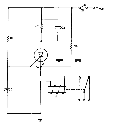
The relay operates for a specific duration, td, after power is applied, followed by an operating time, tc. The SCR activates when the voltage across capacitor Ci reaches a threshold voltage, VA. This action energizes the relay, which remains...
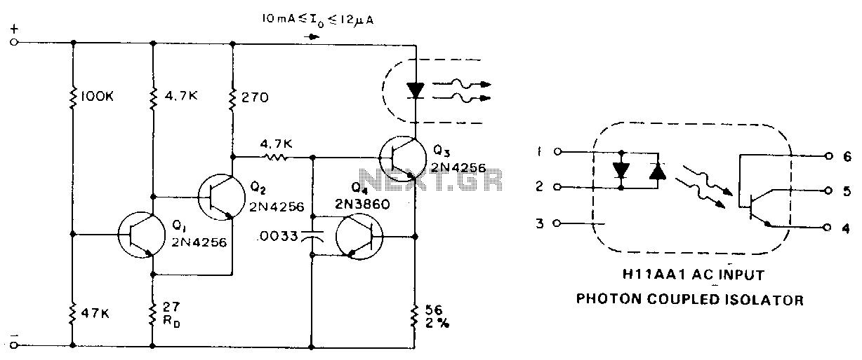
When analog signals serve as the logic control, hysteresis from a Schmitt-trigger input can be utilized to prevent high-wave power output. The circuit functions as follows: at low input voltages, Q1 is biased in the off state. Q2 conducts...
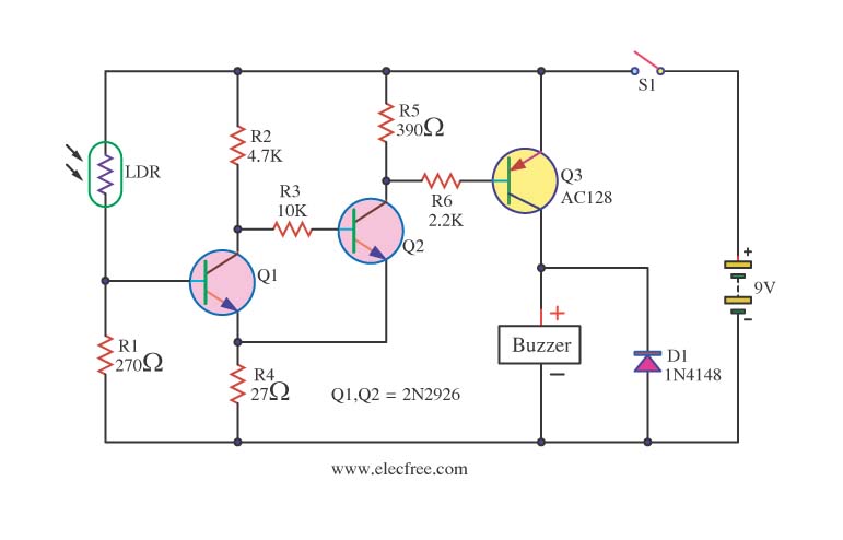
This circuit activates a warning when it becomes dark, functioning as a light-sensitive switch. The essential electronic components include the 2N2926 and AC128 transistors. The described light-sensitive switch circuit is designed to detect ambient light levels and activate an output...