
relay development board for atmega16

This development board is designed for applications requiring robust control and interfacing capabilities. The high-power relays enable the switching of substantial loads, making it suitable for automation and control systems. The inclusion of opto-coupled inputs provides electrical isolation between the control logic and the input signals, enhancing safety and reducing noise interference.
The power supply circuit is engineered to deliver stable voltage levels necessary for the operation of the board and its connected components. A crystal oscillator circuit is integrated to provide accurate timing references, crucial for synchronous operations and communication protocols.
The RS232 port facilitates serial communication, allowing the board to interface with computers and other devices for data exchange. The presence of ICSP (In-Circuit Serial Programming) and JTAG (Joint Test Action Group) ports supports programming and debugging of microcontrollers directly on the board, enhancing development efficiency. The JTAG connector, configured in a 5x2 pin layout, allows for easy connection to external debugging tools, enabling developers to monitor and control the microcontroller's operation during development and testing phases.
Overall, this development board is a versatile platform suitable for a range of electronic projects, providing essential features for both prototyping and final application development.Development board with high power relays, opto-coupled inputs, power supply circuit, crystal oscillator circuit, RS232 port, with ICSP and JTAG ports! JTAG 5x2 pin connector for in-circuit .. 🔗 External reference
Related Circuits
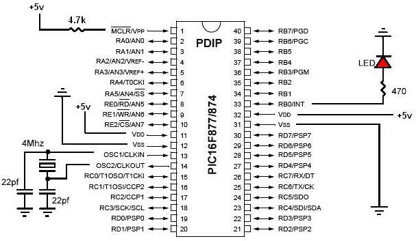
PIC development/testing board. This is a PCB design for a basic PIC16F877 development board. All that is required is a 4 MHz crystal, two 22 pF capacitors, and one 4.7 kΩ resistor. The PIC16F877 development board is designed to facilitate...

The circuit design philosophy allows for debugging without any RF instruments. Although its performance may not match that of professional equipment, it should be adequate for hobbyists, with audio-visual transmission effects comparable to general-purpose machines. The transmitter consists of...
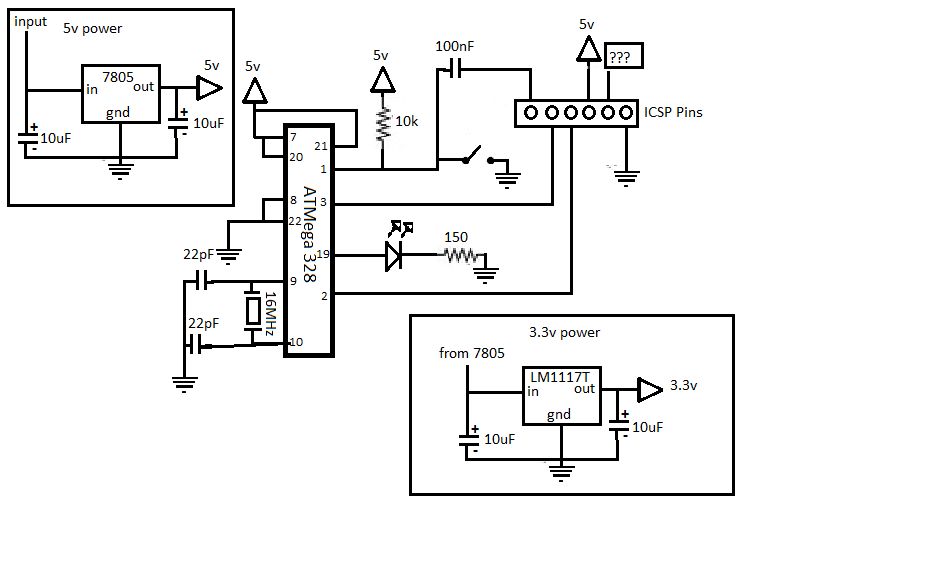
If you are interested in working with Arduino, you may have considered creating your own Arduino board. Creating a custom Arduino board can be an enriching project that allows for greater flexibility and personalization in electronic designs. The process typically...
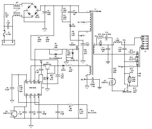
A high brightness LED evaluation board has been developed using the Fairchild Semiconductor FAN7554D PWM controller. The evaluation board for high brightness LEDs incorporates the Fairchild Semiconductor FAN7554D PWM controller, which is designed to provide efficient power management and precise...
This project is designed to assist in a basic course where students create a simple AVR/Arduino-based badge. It serves as a beginner's soldering project, resulting in a small object with blinking lights that can be worn around the neck...
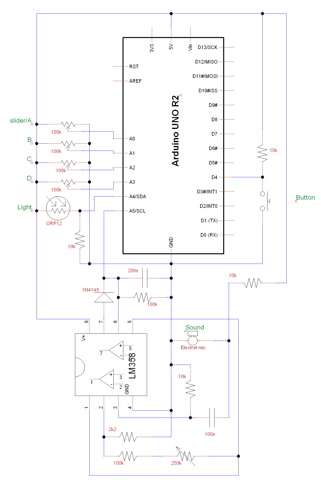
A circuit and Arduino code are designed to emulate a ScratchBoard approximately. The setup includes sound, light, a button, and four sliders, but it is not a direct replacement. It is important to change the COM ports in the...