
Water Meter Monitor
The described water monitoring system employs a positive displacement disk meter, which effectively measures water flow through its mechanical components. The disk meter's operation hinges on the interaction between the water flow and a magnet situated within the collection unit. As water passes through, it causes the magnet to spin, thereby generating a magnetic field that is detected by the Hall-effect sensor.
The Hall-effect sensor is strategically placed to capture the magnetic field fluctuations produced by the rotating magnet. Each complete revolution of the magnet corresponds to a specific volume of water, which in this case is determined to be 0.01 gallons. This high degree of sensitivity allows for accurate tracking of water usage, with the sensor outputting a pulse for each revolution, resulting in a count of 100 pulses per gallon.
To implement this system, the sensor must be properly calibrated to ensure that it accurately counts the revolutions of the magnet. The integration of this sensor with the Power Node enables real-time monitoring and data accumulation, which can be accessed through the Home Control Program. The software updates allow for seamless communication between the sensor data and the monitoring system, providing users with precise information regarding water consumption.
For optimal performance, it is essential to consider factors such as sensor placement, environmental influences, and potential interference from nearby electronic devices. Additionally, testing with various Hall-effect sensors may yield better results, especially in varying flow conditions. The overall design and implementation of this water monitoring system demonstrate a sophisticated approach to resource management, leveraging modern sensor technology to achieve high-resolution data collection.I have been able to monitor the power usage of the home with the Power Node. One project I have been meaning to tackle is to monitor the water usage as well. The photo below shows my main water meter. I also have a "sub-meter", which measures the water usage in the garden. I do not pay for sewer charges for water used by this latter me ter, saving me a lot of money during the growing season. The unit is a " disk meter " which is a positive displacement type. The meter consists of two parts: the collection unit, and the counter unit. Water flows through the sealed collection unit and turns a magnet to transfer the water usage information to the counter unit which sits on top and has the dials. The spinning magnetic field allows the collection unit to be completely sealed for long life. The counter unit also has a remote display mounted outside the home for easy reading by the utility company.
The meter sends one pulse down to the remote unit for every 100 gallons of water used. My first idea for a sensor explored the pulse that the counter unit sends to the remote display unit. Unfortunately, one pulse is sent for every 100 Gallons, and this is much too low a resolution for my use.
My second idea was to pick up the small white arrow on the water indicator dial (marked "10 Gallons" on the front dial) using an optical reflective sensor. Since this indicator makes one revolution per 10 Gallons, I decided to use four phototransistors arranged in a circle to increase the resolution to 2.
5 Gallons. I built the LED and phototransistor circuit and mounted it onto a small piece of perforated printed circuit board and a solderless breadboard. In actual tests I found that it was very difficult to pick up the small white arrow. I was concerned with the difficulty in aligning the sensor over the dial`s window, and drift with voltage and temperature.
After a few days of optimizing parameters such as component values and sensor placement, I gave up on this idea. My third idea exploits the fact that water usage information is transferred magnetically from the collection unit to the counter unit.
This means that the flow of water causes a spinning magnetic field. I wondered if I could pick up water flow information by sensing this magnetic field. My initial tests with a simple magnetic field sensor - a compass - proved promising. As water flows, the compass needle flickered at a rate proportional to water flow. I use a miniature Hall-effect magnetic sensor switch in my weather node`s anemometer, and decided to see if this sensor could pick up the field of the spinning magnet in the collection unit. To my delight, this worked, and I was able to have the sensor produce a pulse for every rotation of the magnet in the collection unit.
Since this magnet spins very fast for a modest usage rate, I would be able to gather water usage with a very high resolution. Note that picking up the water flow by inductive means will not work very well. At high flow rates, and a fast magnetic field, an inductor may work, but at very low flow rates, the coupling will be almost nonexistent.
You may have to experiment with various sensors, or use one on Digi-Key`s website. I was able to find several units that appear identical to the one I have. While filling a container, I observed the number of counts detected from the sensor. I measured 100 counts per gallon, and since this is a nice round number, I presumed that the designers` intended for 0. 01 gallons per revolution of the drive magnet. Being able to measure the water usage down to the nearest one hundredth of a gallon is quite amazing to me, as this is much higher resolution than I need.
Since this is essentially a digital measurement, the reliability is very high. The software on the power node was updated to keep track of the number of pulses on this sensor, and the accumulated byte is sent to the Home Control Program when queried. A 32 🔗 External reference
Related Circuits
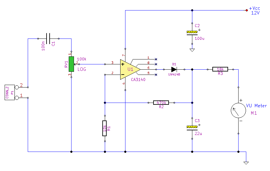
This simple circuit, designed with a minimal component count, indicates peak audio response on an analog meter, similar to a tape recorder's meter. It employs an operational amplifier configured as a non-inverting amplifier, with the addition of a diode...
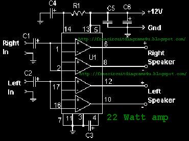
The function of the sound level display circuit is to enhance the appearance of an amplifier circuit or a radio player. It provides an impressive visual representation of audio levels. The sound level display circuit serves as a visual indicator...
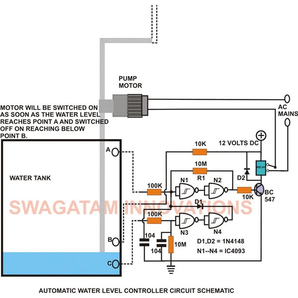
This low-cost water level controller circuit, when built and installed, will efficiently control the water level inside any attached water tank. It helps save electricity and water while relieving users from the hassle of manually switching the water pump...
This is an easy to build, but nevertheless very accurate and useful digital voltmeter. It has been designed as a panel meter and can be used in DC power supplies or anywhere else it is necessary to have an...
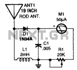
This basic field-strength meter offers an affordable solution for monitoring an amateur radio or CB transmitter, as well as an antenna system, to ensure maximum output. The field-strength meter is designed to measure the strength of radio frequency (RF) signals...
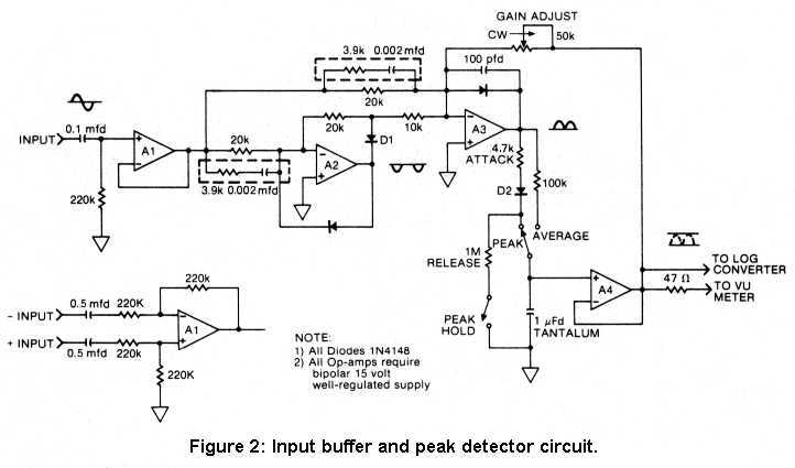
Peak reading meters, popular in Europe for years, are just now coming into greater favor in America, and for good reason. The main purpose for having a VU meter is obviously to monitor signal levels going to a tape...