Data Line Remote Short Sensor
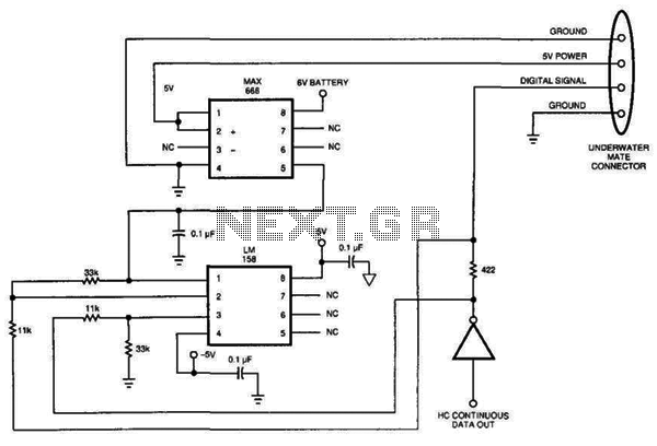
Sensing short circuits in equipment that operates underwater is particularly important. The wet-mat connector design shown in Figure 20-4 is also suitable for other remote short-circuit sensing applications. Due to the limitations imposed by the battery and voltage levels, the circuit utilizes the data line to detect short circuits. The differential voltage that develops across the 422-ohm resistor in the data line drives a low-bandwidth operational amplifier (op amp), which amplifies and filters the differential signal. The resistor values yield a gain of 3. The output of the op amp controls the shutdown pin of the voltage regulator. For proper operation, the circuit requires a continuous stream of digital data. Under normal conditions, using high-speed CMOS logic, the data source sinks less than 10 mA. This normal operation generates approximately -3 mV across the sense resistor. The output of the op amp will be slightly negative, providing a solid "on" signal to the voltage regulator chip. When a short circuit occurs, the resistor and op amp together produce an average of 2.4 Vdc, which provides a solid "off" signal to the voltage regulator chip. The peak signal-line current is about 12 mA (5-V data divided by 422 ohms), which is manageable by HCMOS logic. The addition of the resistor and op amp only increases the rise time to about 40 ns and does not interfere with the 2.5-MHz data rate. Once the short circuit is no longer present, the voltage regulator chip turns on again. This circuit can be applied with any TTL on/off-type voltage regulator integrated circuit (IC).
The circuit for short circuit detection in underwater equipment employs a robust design that integrates a low-bandwidth operational amplifier with a data line sensing mechanism. The operational amplifier is configured to amplify the differential voltage across a 422-ohm resistor, which serves as the sensing element. The gain of 3 is achieved through careful selection of resistor values, allowing for effective detection of small voltage changes indicative of a short circuit.
In normal operation, the circuit is designed to work with high-speed CMOS logic, where the data source typically sinks less than 10 mA. This condition results in a negligible voltage drop of approximately -3 mV across the sense resistor, which is sufficient to keep the op amp output slightly negative. This negative output is interpreted as an "on" signal by the voltage regulator chip, ensuring that the system remains operational under normal conditions.
Upon the occurrence of a short circuit, the sensing mechanism reacts by generating an average voltage of 2.4 Vdc across the op amp output. This significant voltage shift triggers the voltage regulator's shutdown pin, effectively turning off the regulator and protecting the system from potential damage. The design ensures that the peak signal-line current remains within safe limits for HCMOS logic, with a calculated peak of approximately 12 mA.
The circuit's design also takes into account the rise time, which is only increased to about 40 ns due to the addition of the resistor and op amp. This minor delay does not adversely affect the overall data rate of 2.5 MHz, ensuring that the system can operate efficiently without compromising performance.
In summary, this circuit is versatile and can be utilized with various TTL on/off-type voltage regulator ICs, making it an effective solution for remote short-circuit sensing applications, particularly in environments where equipment is submerged underwater. Sensing short circuits in equipment that performs under water is especially critical, but Fig. 20-4"s wet-mat e connector design also suits other remote short-circuit sensing applications. Because of the limits imposed by the battery and voltage levels, the circuit uses the data line to sense short circuits. The differential voltage that develops across the 422- resistor in the data line drives a low-bandwidth op amp, which amplifies and filters the differential signal.
The resistor values produce a gain of 3. The op amp"s output controls the voltage regulator"s shutdown pin. To operate correctly, the circuit must have a continuous stream of digital data. Under normal conditions, and using high-speed CMOS logic, the data source sinks less than 10 . This normal operation generates about -3 mV across the sense resistor. The op amp"s output will be slightly negative, producing a solid on signal to the voltage-regulator chip. When a short occurs, the resistor and op amp together produce an average of 2.4 Vdc. This voltage provides a solid off to the voltage-regulator chip. The peak signal-line current is about 12 mA (5-V data divided by 422 ), which HCMOS logic can handle.
The addition of the resistor and op amp only changes the rise time to about 40 ns and doesn"t cause any problems with the 2.5-MHz data rate. When the short is no longer present, the voltage regulator chip turns on again. You can use the same circuit with any TTL on/off-type voltage-regulator IC. 🔗 External reference
