
waterpump safety guard for fish
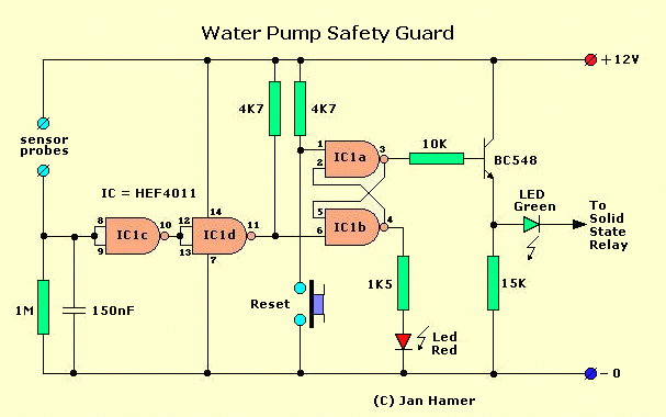
The circuit utilizes a Solid State Relay (SSR) to control the operation of the pump, ensuring that it only runs when the water level is adequate. The sensor, constructed from two copper wires, acts as a level detector. When submerged, the water's conductivity allows a voltage signal to be sent to the input of IC1c, a comparator or logic gate, which changes the state of the output at IC1d. This output is responsible for controlling the SSR, which in turn powers the pump.
The circuit includes visual indicators in the form of LEDs. The green LED signifies that the pump is operational and the water level is adequate, while the red LED alerts the user to a problem, such as low water level. The Reset switch provides a manual method to restore normal operation after maintenance, ensuring that the pump can be safely restarted without the risk of damage due to low water conditions.
The use of a Flip-Flop allows for a reliable state change that can indicate the operational status of the pump and the water level condition. This design minimizes the need for constant monitoring while providing clear visual feedback and a straightforward reset mechanism, making it user-friendly and efficient for maintaining optimal conditions in the fish pond.The circuit below was developed to guard the fish pond. In this case to prevent that the pump sucks just air when the waterlevel get below the pump. When the waterfilters get saturated and dirty, the water level behind the filter gets to an unacceptable level. You can see this when the pump also produces airbubbles in the water. Because you are no t all day peeking if this is the case, I connected the pump via a Solid State Relais, which acts as a power switch mounted in one of the AC wires and is controlled by the circuitry below. The sensor is fabricated using two sturdy solid *copperwires which are mounted approximately 1cm () apart in the water after the waterfilter.
The conductivity of the water is sufficient to pull the input of the first IC (IC1c) high. The output of IC1d will then also be high. (* see note) Often the condition is correct when you power up, which is indicated by the green led. However, if the red led is lit, just press the Reset switch to put the circuit in the proper operational condition. The current flowing through the green led is also fed through the diode in the Solid State Relay, activating the relays and the starting the pump.
If for some reason the water level is getting low and the copper wires no longer touch the water, the input of the first IC is pulled low and consequently also the ouput of the IC behind that. The R-S Flip-Flop flips to the other condition and the green led goes out and also the pump and the red led will be lit to indicate `something` is wrong.
In this case the waterlevel. When you`re ready after the filters have been cleaned, the only you have to do is press the Reset button to activate the pump again. This way unnecessary damage to the pump is prevented. 🔗 External reference
Related Circuits
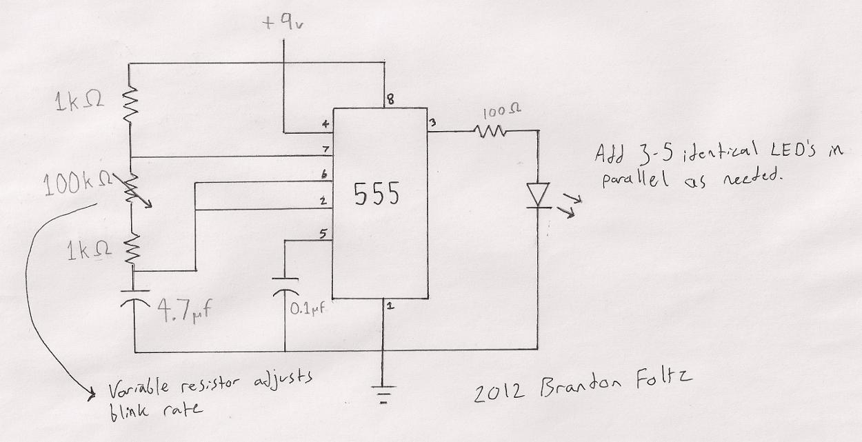
The circuit utilized is a commonly known design. A search for "555 timer LED blinker" will yield numerous schematics that are suitable for this application. The specific schematic presented includes a variable resistor (100K) that allows for user-adjustable blink...
Protect home appliances from voltage spikes using this simple time delay circuit. This circuit activates when power to the appliances is switched on or resumes after a power outage. The time delay circuit is designed to safeguard sensitive electronic devices from...

This circuit provides protection for telephones, EPABX systems, telephone modems, and similar devices against lightning discharges and line voltage spikes. It incorporates a safety capacitor and gas discharge components. The circuit employs a safety capacitor to filter out high-frequency noise...

This circuit is designed to protect telephones, EPBX systems, telephone modems, and similar devices from lightning discharges or line spikes. It employs a safety capacitor and a gas tube arrester to prevent damage to the devices. While the circuit...
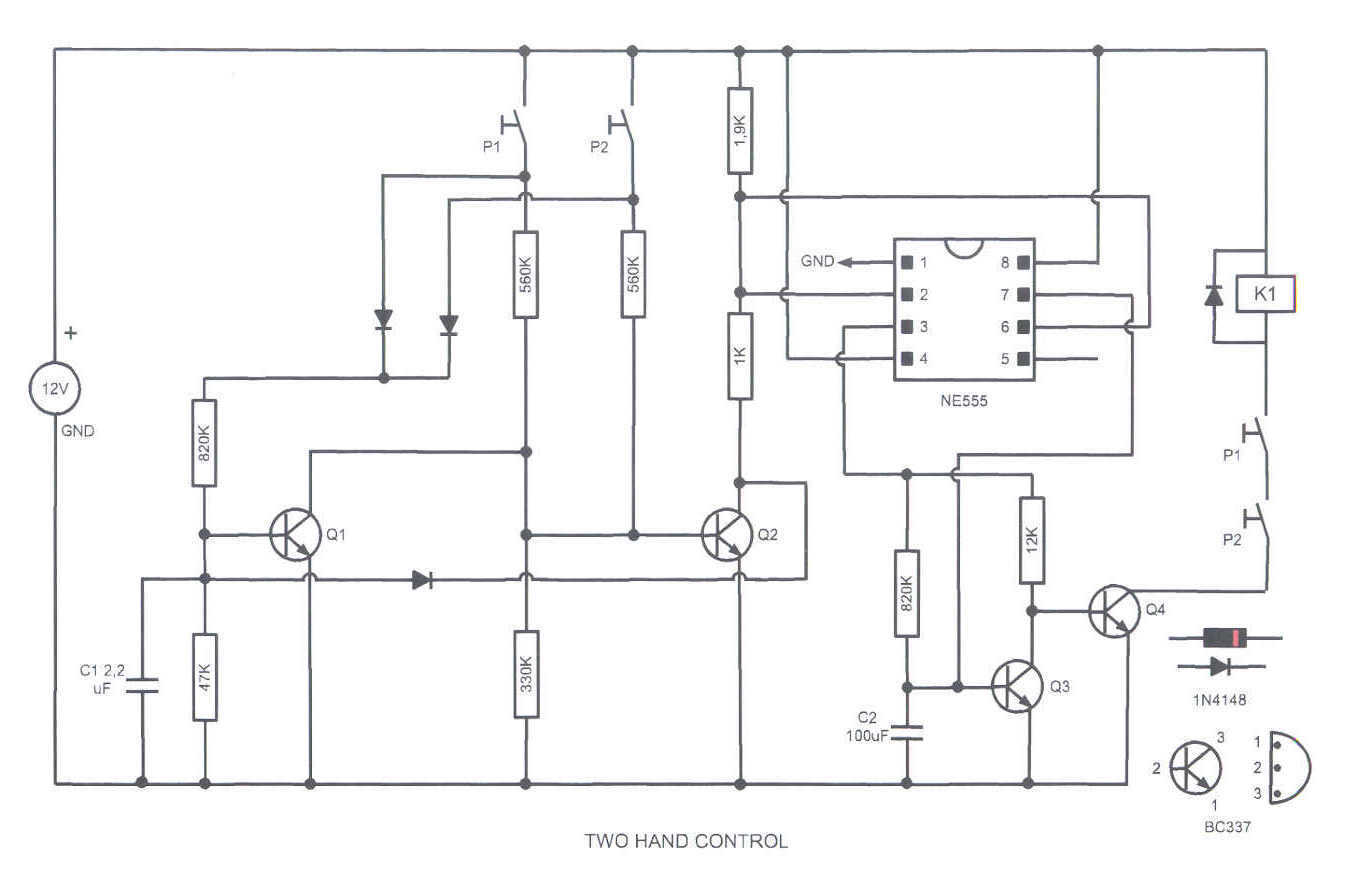
This circuit turns on a relay when two buttons are pressed at the same time. The relay backs off after a few seconds, then the buttons have to be released and pressed again. This feature is often required in...
How to turn on equipment by sending SMS `1111` to switch it ON and switch off the equipment by sending SMS `0000`. The GSM switch will receive instructions for either load 1 (L1), load 2 (L2), load 3 (L3),...