
White LED Array Lamp
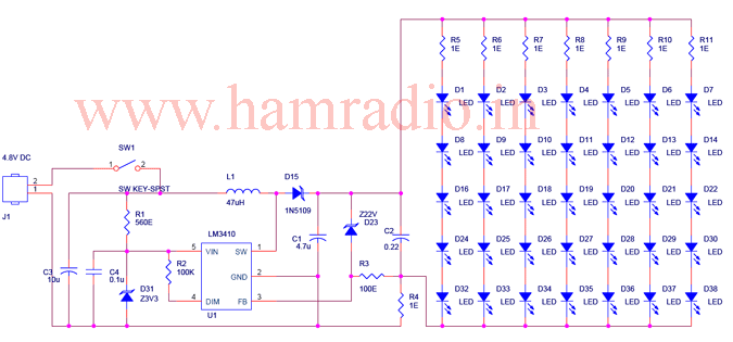
This battery-operated LED lamp circuit offers an efficient and effective solution for ambient lighting. The use of a low-power discrete LED array ensures a softer light output, making it more comfortable for prolonged viewing. The LM3410 integrated circuit provides robust performance with high efficiency, minimizing energy waste and extending battery life. The external components required for the circuit are minimal, making assembly straightforward. The choice of a 525 kHz switching frequency balances the need for compact components while ensuring low core losses in the inductor, which is crucial for maintaining high efficiency.
The design accommodates the need for brightness control through PWM dimming, allowing users to adjust the light output according to their preferences. The inclusion of over-voltage protection enhances the reliability of the circuit, ensuring that the LED array operates safely under various conditions. The standby current of only 80 nA is particularly advantageous for battery-operated applications, as it extends the operational life of the batteries between charges.
Overall, this LED lamp circuit is well-suited for applications where low power consumption, ease of assembly, and user-adjustable brightness are essential. Its design principles can be adapted for various lighting scenarios, making it a versatile choice for portable lighting solutions.To make a battery operated LED lamp, it may better to use a cluster of low power discrete LED array rather than a single high power LED. The light produced will be scattered and It considerably reduces irritation or damages to a naked eye, if accidentally looked on it.
Also the light spreads nicely so it is good for room lighting and no heat sink required for the LEDs! The circuit is designed to operate 3W, 5 x 7 white LED array powered from four NiMH cells. The design is straight forward DC to DC boost circuit using a LM3410 which includes a 170 m © NMOS switch. The circuit is completes with few external components. The switching frequency is internally set to either 525 kHz for LM3410-Y devices or 1. 60 MHz for LM3410-X, allowing the use of extremely small inductors and capacitors. The 525 kHz switching frequency is selected due to the availability of suitable ferrite having lower core losses.
The inductor value needed for the circuit depends upon the voltage and current output needed. A detailed calculation is described in the datasheet of the LM3410. A higher efficiency of approximately 88% is achieved. The IC is featured with an external shutdown and the standby current of only 80 nA. The operating current for a single branch the LED array is ~25mA, and since there are 7 parallel paths a total output current of 190mA is drawn from the DC to DC convertors. This current is set by the 1O resistor R4 (I = 0. 19/R4). An optional output over voltage protection is provided using a 22V zener diode D23 and a resistor R3.
This will protect the IC if the LED load becomes an open circuit. Since the absolute maximum input voltage to the IC is 5. 5 V, a voltage regulator using R1 and zener diode D31 is required if the circuit is operated from a voltage source more than 5. 5 V. The DIM input pin of LM3410 can be used for either on/off or brightness control of LED array. A PWM dimming signal whose duty cycle from 0 to 100% with a frequency of 200 ~ 1 kHz is best suited for this brightness control, although a PWM with maximum of 25 KHz can be used.
In this application DIM pin is tied to VIN for maximum brightness. 🔗 External reference
Related Circuits
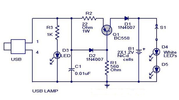
A simple USB-powered lamp designed to illuminate a desktop during power outages. The circuit operates at 5 volts sourced from a USB port. The 5V from the USB is directed through a current-limiting resistor (R2) and a transistor (Q1)....
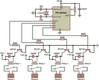
This is a relay driver based on a PIC16F84A microcontroller. The board includes four relays, allowing control of four distinct outputs. The relay driver circuit utilizing the PIC16F84A microcontroller is designed for controlling multiple devices or systems through relay activation....
The circuit includes a CD4 component with a connection of 16 feet for the Vcc terminal, 8 feet for the ground, 12 feet for the reset terminal, 7 feet for the Qt end, and 3 feet for the Q...
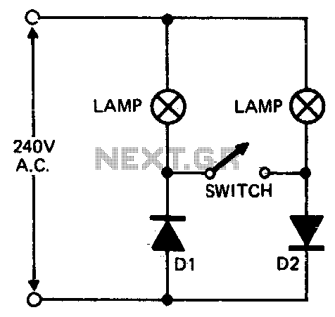
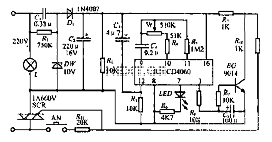
When setting up photographic floodlamps, it is sometimes desirable to operate the lamps at lower power levels until actually ready to take the photograph. The circuit allows the lamps to operate on half-cycle power when the switch is open...
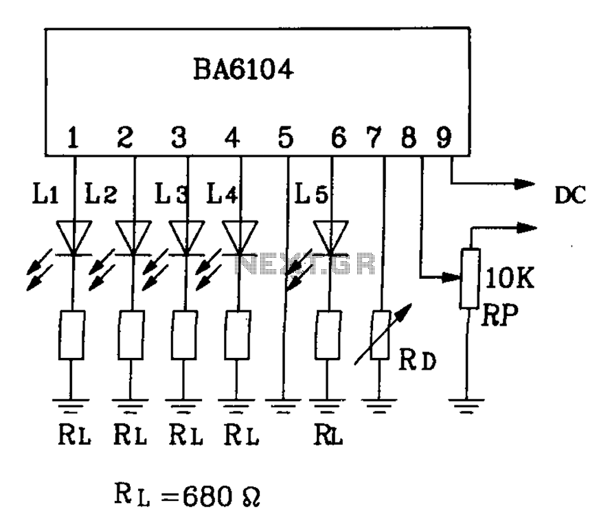
BA6104 is a five-digit LED level meter driver integrated circuit (IC) that features a basic application circuit. The input stage employs a PNP transistor with a composite base input, resulting in high input impedance. The output stage is configured...

The circuit depicted in Figure 3-69 is designed for applications requiring frequent timing control for motor reversing operations. In this configuration, thyristors V1, V2, V7, and V5 are utilized for positive control of rotation, while thyristors V3, V4, and...