
white led driver provides 64
This circuit employs a charge pump design to effectively drive multiple white LEDs from a low-voltage source, making it suitable for battery-operated devices. The ability to control the current in a logarithmic scale is particularly beneficial for applications requiring fine-tuning of brightness levels, such as in display backlighting or decorative lighting. The charge pump operates by utilizing the current from the SET terminal of operational amplifier U3, which is precisely regulated at 0.6V to ensure stable operation across varying load conditions.
The op-amp U2 plays a crucial role in maintaining the desired brightness by continuously monitoring the voltage difference between the high-side supply voltage and the wiper voltage of the digital potentiometer U1. This feedback mechanism allows for dynamic adjustment of the output current, ensuring that the brightness remains consistent even if the supply voltage fluctuates. The digital potentiometer, which features a logarithmic taper, is key to achieving the desired dimming effect, providing a smooth transition between brightness levels across its range.
The implementation of a 16-bit serial interface for controlling the digital potentiometer allows for precise adjustments, with each tap corresponding to a 1dB change in brightness. This level of control is paramount in applications where user experience is enhanced by gradual dimming rather than abrupt changes in light output. The circuit's design also accommodates a "mute" function, enabling the user to set the LED current to a minimum level without completely turning off the LEDs, which can be useful in certain operational scenarios.
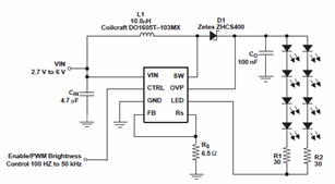
In summary, the described circuit combines a charge pump with a sophisticated control mechanism to provide adjustable illumination for white LEDs, making it an effective solution for portable and power-sensitive applications. The careful consideration of component selection and circuit design ensures reliable performance and user-friendly operation.This circuit drives as many as four white LEDs in parallel from a 3. 3V source, and adjusts the total LED current from 1mA to 106mA, in 64 steps of 1dB each. The circuit of Figure 1 is designed for portable-power applications that require white LEDs with adjustable, logarithmic dimming levels. It drives as many as four white LEDs from a 3 . 3V source, and adjusts the total LED current from 1mA to 106mA in 64 steps of 1dB each. The driver is a charge pump that mirrors the current ISET (sourced from U3`s SET terminal), to produce a current of (215ISET ±3%) through each LED. Internal circuitry maintains the SET terminal at 0. 6V. To control the LED brightness, op amp U2 monitors the difference between the high-side voltage and the wiper voltage of digital potentiometer U1.
The op amp then multiplies that voltage by a gain to set the maximum output current. Zero resistance at the pot`s W1 terminal corresponds to minimum LED current, and therefore minimum brightness. Because the SET voltage is fixed (at 0. 6V), any voltage change at the left side of R5 changes ISET, and the resulting change in LED currents changes their brightness level.
R5 sets the maximum LED current: U1 is a digital potentiometer with logarithmic taper and an analog-voltage wiper for which each tap corresponds to 1dB of attenuation between H1 and W1 (pins 11 and 9). It contains two pots controlled by a 16-bit code via a 3-wire serial interface. To set the LED current, drive RST-bar high and clock 16 bits into the D terminal of U1, starting with the LSB.
Each pulse at CLK enters a bit into the register. The circuit uses only one pot, so bits 0 through 7 are "don`t care" bits. Bits 8 through 14 determine the wiper position: bits 8 through 13 set the code, and bit 14 is "mute. " (Logic one at bit 14 produces the lowest-possible output current by setting the left side of R5 at approximately 0. 599V. ) After entering all 16 bits, enter the code and change the brightness level by driving RST-bar high.
Figure 2 shows the logarithmic relationship between an LED current and the pot`s input code. 🔗 External reference
Related Circuits
The schematic diagrams for the TPS61042 current LED driver illustrate its capability to power eight LEDs with an efficiency of 81% at 3.6V and 18.6mA. The TPS61042 is commonly utilized in applications such as white LED supply for backlight...
This is a 0 - 6 MHz DDS VFO controlled by a PIC16F84 (or C84). The VFO is separated into two modules, the DDS module and the controller module. The PCB layout (double sided) for the DDS module is...
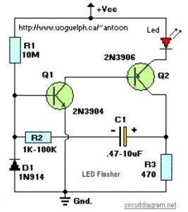
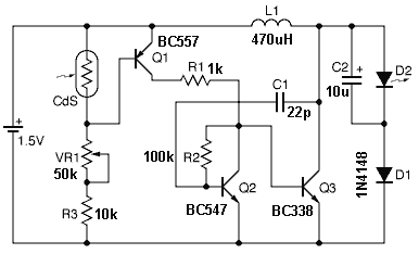
This circuit is designed to flash a high-brightness red LED (5000 mcd), making it suitable for use in fake car alarms or other devices intended to attract attention. The specific values of the components are not critical, allowing for...
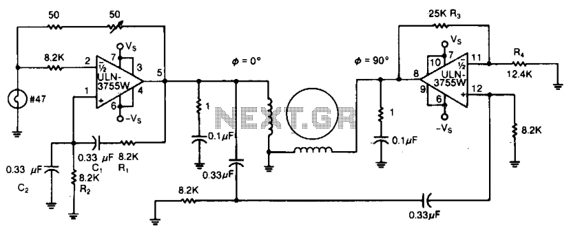
Due to its high amplification factor and integrated power-output stage, an integrated power operational amplifier serves as an effective driver for AC motors. One operational amplifier can be configured as an oscillator to generate the necessary AC signal. The...
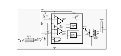
This circuit is designed around a 555 timer and utilizes a minimal number of components. Due to its simplicity, it can be easily constructed and operated by beginners. The circuit leverages the 555 timer IC, which is a versatile and...
It is essential to draw a circuit using a layout and conventions that are universally recognized. In electronic circuit design, adherence to standardized symbols and layout conventions is crucial for effective communication among engineers and technicians. A well-drawn schematic diagram...